Beehive 11-4FZ
Kriesler Radio Company; Newtown (Sydney)
- Paese
- Australia
- Produttore / Marca
- Kriesler Radio Company; Newtown (Sydney)
- Anno
- 1946–1948

- Categoria
- Radio (o sintonizzatore del dopoguerra WW2)
- Radiomuseum.org ID
- 205442


Clicca sulla miniatura dello schema per richiederlo come documento gratuito.
- Numero di tubi
- 4
- Principio generale
- Supereterodina (in generale); ZF/IF 455 kHz; 2 Stadi BF; Reflex
- N. di circuiti accordati
- 6 Circuiti Mod. Amp. (AM)
- Gamme d'onda
- Onde medie (OM) e corte (OC).
- Tensioni di funzionamento
- Alimentazione a corrente alternata (CA) / 220; 240 Volt
- Altoparlante
- AP magnetodinamico (magnete permanente e bobina mobile) / Ø 5 inch = 12.7 cm
- Materiali
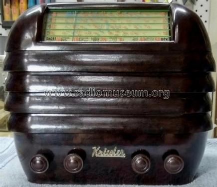
- Bachelite
- Radiomuseum.org
- Modello: Beehive 11-4FZ - Kriesler Radio Company;
- Forma
- Soprammobile compatto/con bordi arrotondati/midget senza pulsantiera/tastiera.<= 35 cm (Sometimes with handle but for mains only).
- Dimensioni (LxAxP)
- 250 x 220 x 210 mm / 9.8 x 8.7 x 8.3 inch
- Annotazioni
-
Kriesler advertised this set & other post-war models as a "Sealed Radio". Solder joints were marked to prevent unauthorised servicing & tampering.
Walnut Bakelite cabinet. Also available in various colours for 1 Guinea (£1/1/-) extra. Price in WA for standard Walnut model, £19/8/6.
There are 36 variants of this model:
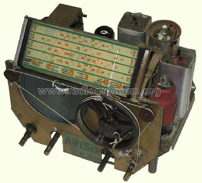
- CIRCUIT: As on 11-4 circuit but with the following alterations:- (Note: Enclosed diagram in lower right hand corner of sheet does not apply).
- Tone control (0.5 Megohm Potentiometer) replaced by 2 position, 0.02 μF 600v. condenser (C95) and 0.5 Megohm ½ watt resistor (R117). Disconnect lead from centre lug of potentiometer, and wire it to stationary contact of switch. Earth moving arm of switch. Replace potentiometer with fixed resistor.
- Power transformer changed from 18-27 to 18-1.
- 6J8G valve replaced by ECH35 converter.
- R103A (15,000 Ω) was replaced by R153A (40,000 Ω), R136 (30,000 Ω) was replaced by R153B (40,000 Ω).
- R139 (50 Ω) was replaced by R157 (20 Ω).
- 5Y3G valve replaced by 6X5GT rectifier, (6X5GT heater connected to 6.3v winding on transformer.
- Speaker 70-1 was replaced by speaker 70-8.
- H.T. choke (28-3) to replace field of 70-1 speaker.
- COIL KIT: Part No. 15-2 (S.C. Tuning Condenser).
- DIAL GLASSES: Part No. 50-12 (Principle section). Part No. 50-25 (Rear glass).
- SPEAKER: Part No. 70-8 (5" Permanent magnet type).
- OUTPUT TRANSFORMER: Part No. 18-26.
- POWER TRANSFORMER: Part No. 18-32 (H.T.: 250v each side of centre tap).
- NOTE: Power transformers 18-32 & 18-6 are interchangable. When 18-32 is used a 400 Ω bias resistor is used. When 18-6 is used a 250 Ω bias resistor is used.
- Prezzo nel primo anno
- 18.90 AUS £
- Riferimenti schemi
- Australian Official Radio Service Manual Vol. VI
- Letteratura / Schemi (1)
- - - Manufacturers Literature (Kriesler Technical Service Instructions.)
- Letteratura / Schemi (2)
- Australian Official Radio Service Manual AORSM (Volume 6, 1948, Page 262.)
- Autore
- Modello inviato da Stuart Irwin. Utilizzare "Proponi modifica" per inviare ulteriori dati.
- Altri modelli
-
In questo link sono elencati 901 modelli, di cui 469 con immagini e 439 con schemi.
Elenco delle radio e altri apparecchi della Kriesler Radio Company; Newtown (Sydney)