Beehive 11-4L Ch= 11-4
Kriesler Radio Company; Newtown (Sydney)
- Country
- Australia
- Manufacturer / Brand
- Kriesler Radio Company; Newtown (Sydney)
- Year
- 1946–1948
- Category
- Broadcast Receiver - or past WW2 Tuner
- Radiomuseum.org ID
- 297576
Click on the schematic thumbnail to request the schematic as a free document.
- Number of Tubes
- 4
- Main principle
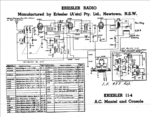
- Superheterodyne (common); ZF/IF 455 kHz; Reflex
- Wave bands
- Broadcast and Short Wave (SW).
- Power type and voltage
- Alternating Current supply (AC) / 220-240 Volt
- Loudspeaker
- Permanent Magnet Dynamic (PDyn) Loudspeaker (moving coil)
- Material
- Bakelite case
- from Radiomuseum.org
- Model: Beehive 11-4L Ch= 11-4 - Kriesler Radio Company;
- Shape
- Tablemodel without push buttons, Mantel/Midget/Compact up to 14
- Notes
-
Kriesler advertised this set & other post-war models as a "Sealed Radio". Solder joints were marked to prevent unauthorised servicing & tampering.
Walnut Bakelite cabinet. Also available in various colours for 1 Guinea (£1/1/-) extra. Price in WA for standard Walnut model, £19/8/6.
There are 36 variants of this model:
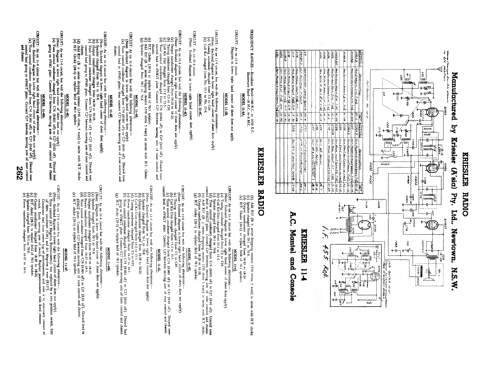
- CIRCUIT: As on 11-4 circuit but with the following alterations:- (Note: Enclosed diagram in lower right hand corner does not apply).
- Speaker changed from 70-1 to 70-8.
- Output transformer changed from 18-28 to 18-26.
- Coil Kit Unit changed from 15-2 to 15-5.
- Tuning Condenser changed from C3 to C95.
- Power transformer changed from 18-27 to 18-1.
- Tone control condenser changed from C74 (0.001 μF) to C27 (0.01 μF). Discard tone control lead to 6V6GT plate. Connect C27 between moving arm of tone control and chassis.
- H.T. Choke (28-3) to replace field of 70-1 speaker.
- COIL KIT: Part No. 15-5 (AWA Tuning Condenser).
- DIAL GLASSES: Part No. 50-10 (Country stations). Part No. 50-11 (Local stations).
- SPEAKER: Part No. 70-8 (5" Permanent magnet type).
- OUTPUT TRANSFORMER: Part No. 18-26.
- POWER TRANSFORMER: Part No. 18-1 (H.T.: 275v each side of centre tap).
PROCEDURE FOR REMOVING CHASSIS FROM CABINET:
- Remove knobs.
- Invert receiver.
- Remove base by breaking seal and unscrewing 4 x 3/16" screws in base of cabinet.
- Remove 4 x 3/16" nuts, situated in the inside corners of the chassis.
- Lay receiver on its back with spindles facing upwards.
- Place one hand each side the of chassis. With the forefingers, exert a downward pressure on the front panel, at the same time withdrawing the chassis from the cabinet.
CHASSIS NUMBERS:
Every receiver that leaves the Kriesler factory is given two chassis numbers.
The "Production" chassis number is stamped on a card. The card is riveted to the main chassis in such a location that the number is able to be read without removing the chassis from the cabinet. The "Production" chassis number is the number that should be quoted, together with the model number, when making enquiries.
The second chassis number (Prefix "0") is stamped into the metal chassis to provide a permanent record.
Both the abovementioned chassis numbers are recorded at the factory.
- Price in first year of sale
- 18.90 AUS £
- Literature/Schematics (1)
- - - Manufacturers Literature (Kriesler Technical Service Instructions.)
- Literature/Schematics (2)
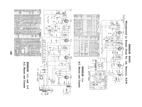
- Australian Official Radio Service Manual AORSM (Volume 5, 1947, Page 188 & Volume 6, 1948, Page 262.)
- Author
- Model page created by Martin Kent. See "Data change" for further contributors.
- Other Models
-
Here you find 901 models, 469 with images and 439 with schematics for wireless sets etc. In French: TSF for Télégraphie sans fil.
All listed radios etc. from Kriesler Radio Company; Newtown (Sydney)