Oscilloscope LA-265A
Lavoie Laboratories; Morganville (NJ)
- Country
- United States of America (USA)
- Manufacturer / Brand
- Lavoie Laboratories; Morganville (NJ)
- Year
- 1964 ?
- Category
- Service- or Lab Equipment
- Radiomuseum.org ID
- 113013

- Number of Tubes
- 78
- Wave bands
- - without
- Power type and voltage
- Alternating Current supply (AC) / 105-250 Volt
- Loudspeaker
- - - No sound reproduction output.
- Material
- Metal case
- from Radiomuseum.org
- Model: Oscilloscope LA-265A - Lavoie Laboratories;
- Shape
- Tablemodel, with any shape - general.
- Dimensions (WHD)
- 13 x 17 x 24 inch / 330 x 432 x 610 mm
- Notes
- The LA-265A is a mainframe oscilloscope with DC to 30 MHz bandpass and 12 ns risetime. Remarkable are the distributed gain vertical amplifier, using 12 6DK6 tubes and the vertical delay line, with 70 LCR adjustable elementary cells.
- Net weight (2.2 lb = 1 kg)
- 30 kg / 66 lb 1.3 oz (66.079 lb)
- Mentioned in
- - - Manufacturers Literature
- Author
- Model page created by Emilio Ciardiello. See "Data change" for further contributors.
- Other Models
-
Here you find 21 models, 16 with images and 0 with schematics for wireless sets etc. In French: TSF for Télégraphie sans fil.
All listed radios etc. from Lavoie Laboratories; Morganville (NJ)
Collections
The model Oscilloscope is part of the collections of the following members.
Forum contributions about this model: Lavoie Laboratories;: Oscilloscope LA-265A
Threads: 1 | Posts: 7
The Lavoie LA-265A was a militarized version of the Tektronix 545A oscilloscope mainframe, of course capable of replacing even other mainframes, as the 531, the 535 and the 541. In the late fifties military asked some suppliers, Hickok, Jettinson and the same Lavoie Laboratories, for second sources of this family of widely used instruments. LA-265A was a true second source for the appreciated Tek mainframes. For this oscilloscope Lavoie also built at least four vertical plug-in amplifiers, the LA-265-D, the LA-265-CA, the LA-265-B and the LA-265-L, fully compatible with Tek D, CA, B and L types. Probably this line was introduced quite late, when the 545A was already a mature instrument, to prevent predictable reactions by Tektronix. We can date its production start up around the early sixties, since the first edition of the related technical manual, T.O. 33A1-13-229, is dated 1 November 1963.
Electrical and mechanical specs given in the manual are the same claimed for the model 545A. They can be summarized as follows:
| Vertical deflection | |
| - Bandpass with a L-type fast rise plug-in: | DC to 30 MHz |
| - Risetime | 12 ns |
| Horizontal sweep | |
| - Triggering modes T-base A | Auto, AC, DC, AC lf reject and AC hf |
| - Triggering modes T-base B | Auto, AC and DC |
| - Triggering level req., internal | Minimum 2 mm vertical deflection |
| - Triggering level, external | Signal between 0.2 and 10 volts amplitude |
| - Sweep times T-base A | 0.1 μs to 5 s per centimeter in 24 calibrated steps. Up to 12 s/cm uncalibrated |
| - Sweep times T-base B | 2 μs to 1 s per centimeter in 18 calibrated steps. |
| - Time base accuracy | 1% typical, 3% max error in calibrated positions |
| Calibrator | |
| Calibrator voltage | 1 KHz square wave, 0.2 mV to 100Vpp in 18 steps. 3% accuracy |
| Power requirements | 115 to 125 and 210 to 250 VAC, 50 to 60 Hz, approx. 600 VA with LA-265-CA plug-in installed |
| Mechanical | |
| Dimensions | 13 by 16-3/4 by 24 inches |
| Weight | 65 pounds or about 30Kg |
The above figures are exactly the same given by Tektronix for its 545A oscilloscope, with the sole exception for power requirements: 500 VA for the 545A, even if with a different vertical plug inserted. Mistype or different test conditions?
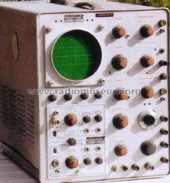
Looking at the front panel of the LA-265A we find that the only barely appreciable differences are in the labels, silkscreened and not engraved, and in the control knobs, with few yet pronounced knurls in the Lavoie model.
 |
 |
Fig. 1 – Here are the front panel of a LA-265A and the panel of a Tek mainframe, a 585A in this case. Same controls and same layout.
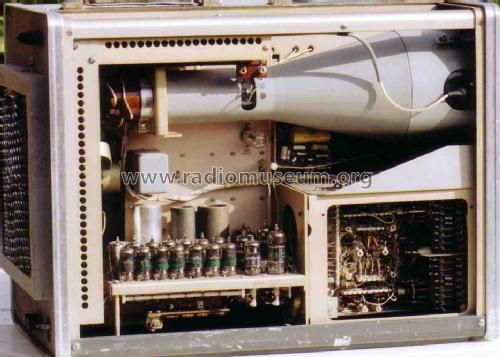
Removing the cabinet side covers, the top class execution of the instrument can be appreciated. Golden-anodized aluminum is used throughout. Side covers are protected by a conductive mesh inside, over the vent slots, to prevent radiation interference.
 |
 |
 |
Fig. 2 – Three views of the inside.
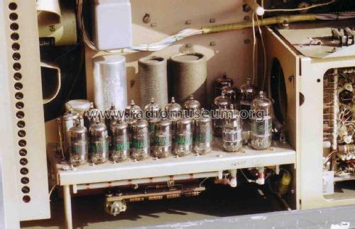
As in Tek scopes, passive components are mounted between rows of ceramic strips. In this case strips show variable spacing between notches, to accommodate components of different diameter. Another difference is the use of little metal tongues clamped to the ceramic strips, instead of metallized notches: this allows the use of standard soldering alloys, instead of the special silver loaded alloy used in Tek scopes. Quite remarkable differences are even in the sealed execution of the power transformer and of the fan motor.
 |
 |
 |
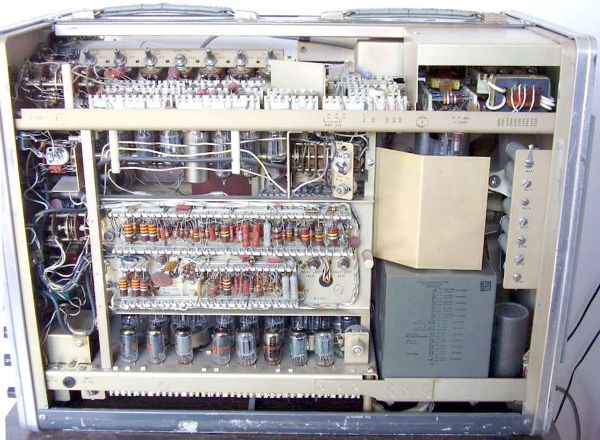
Fig. 3 – Details of the time-base B, beside the power supply section, and of the sealed power transformer. The last picture on the right shows the HV stabilizer subassembly.
The most relevant departure from the solutions of the Tektronix 535A is in the CRT electron gun biasing circuit. Here Lavoie replaced the simple resistive voltage divider used by Tektronix with a voltage stabilization circuit, based upon a series of 31 NE-2 neon bulbs. These bulbs are potted with clear silicone compound inside a small aluminum can, its opening downward looking, and give a bright light all over the vertical amplifier section in normal operation. Details of this section are given in fig. 3c.

Fig. 4 – Schematic diagram of the original CRT H.V. supply. Each NE-2 in the B801 voltage stabilizer subassembly gives a typical voltage drop of 59 volts.
The above said overrefinement was eventually the source of the major drawback of this instrument. The voltage drop in the neon bulbs increases with their ageing, causing instability and fading of the trace brightness. The original circuit, showing the taps added to recover some ageing of neon bulbs, is given in fig. 4 above. In case of a probable failure of some neon bulbs, the simplest remedy today is to replace the entire subassembly either with suitable corona-discharge voltage stabilizers or with a series of zener diodes, as in the diagram below.

Fig. 5 - Here is the zener based circuit used to bring back to life the LA-265A in the pictures.
Emilio Ciardiello, 03.Jan.12