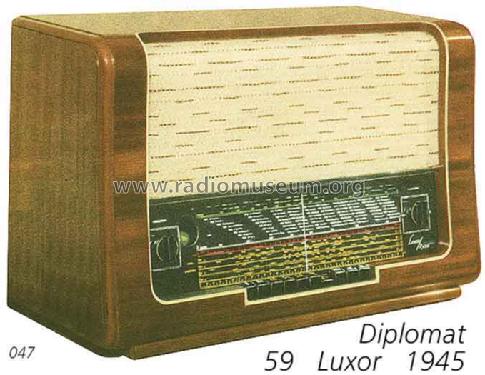
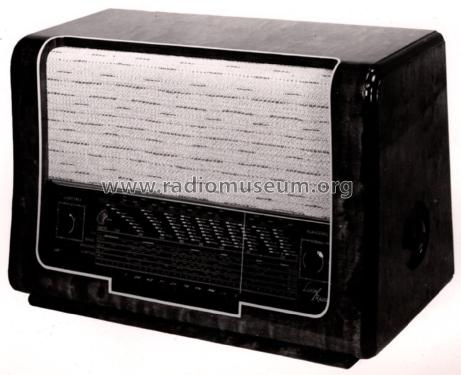
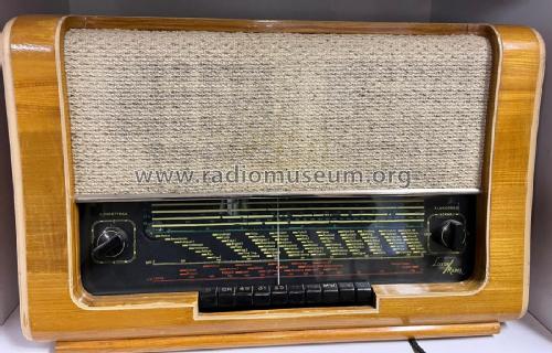
Diplomat 59W
Luxor Radio AB; Motala
- Country
- Sweden
- Manufacturer / Brand
- Luxor Radio AB; Motala
- Year
- 1945/1946
- Category
- Broadcast Receiver - or past WW2 Tuner
- Radiomuseum.org ID
- 18201
-
- alternative name: Luxorita - voir Luxor Radio AB Suède (Sweden)
aukro.cz/radio-luxor-top-stav-7058532442
aukro.cz/radio-luxor-top-stav-7058532442
aukro.cz/radio-luxor-top-stav-7058532442
Click on the schematic thumbnail to request the schematic as a free document.
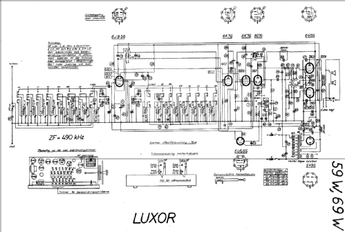
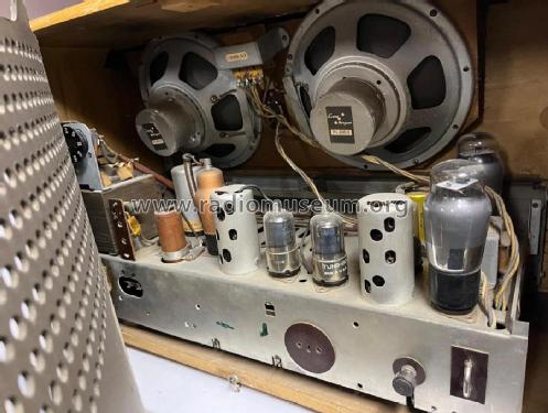
- Number of Tubes
- 8
- Main principle
- Superheterodyne (common)
- Wave bands
- Broadcast, Long Wave and more than two Short Wave bands.
- Power type and voltage
- Alternating Current supply (AC)
- Loudspeaker
- Permanent or electro-dynamic (moving coil), system not known yet.
- Material
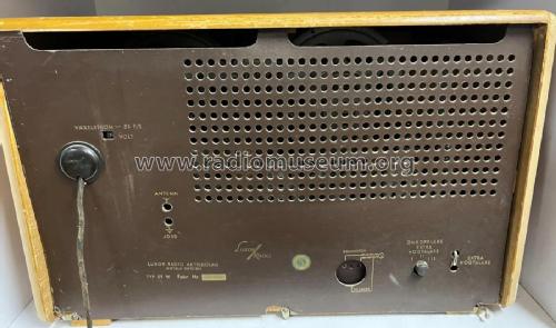
- Wooden case
- from Radiomuseum.org
- Model: Diplomat 59W - Luxor Radio AB; Motala
- Dimensions (WHD)
- 620 x 390 x 280 mm / 24.4 x 15.4 x 11 inch
- Notes
- 4 x KW
- External source of data
- E. Erb 3-907007-36-0
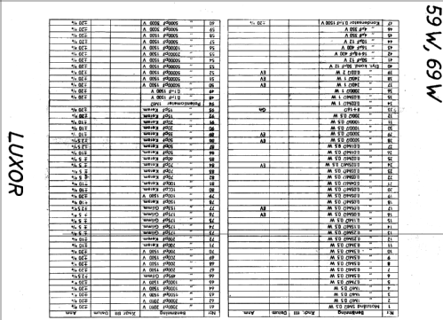
- Circuit diagram reference
- Die «Thali Schemasammlung» führt das Modell.
- Picture reference
- Das Modell ist im «Radiokatalog» (Erb) abgebildet.
- Other Models
-
Here you find 399 models, 306 with images and 141 with schematics for wireless sets etc. In French: TSF for Télégraphie sans fil.
All listed radios etc. from Luxor Radio AB; Motala
Forum contributions about this model: Luxor Radio AB;: Diplomat 59W
Threads: 1 | Posts: 1
The AF section has a push-pull output stage with a CR-RC-net between preamp and output stage to shift phase. In addition the net is condemned to work as a tone control, too.
Both of the 6V6 get the signal from the plate of the preamp stage. In order to save the phase splitter stage or to evade patents, the model shifts phase with two caps.
Values of the parts were taken from a friend.'s unit. He also took output power measurements: Full power of 5 Watts at 10% distortion is reached only at 1kHz and switch position R21 grounded. Besides of 1kHz loss of power is dramatic, -4.4dB at 500Hz/3kHz, -6dB at 250Hz/4kHz.
Marc Gianella, 07.Feb.10