- Land
- Italien / Italy
- Hersteller / Marke
- Magnadyne Radio; Torino
- Jahr
- 1951/1952
- Kategorie
- Rundfunkempfänger (Radio - oder Tuner nach WW2)
- Radiomuseum.org ID
- 113297
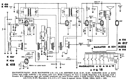
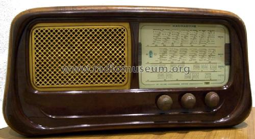
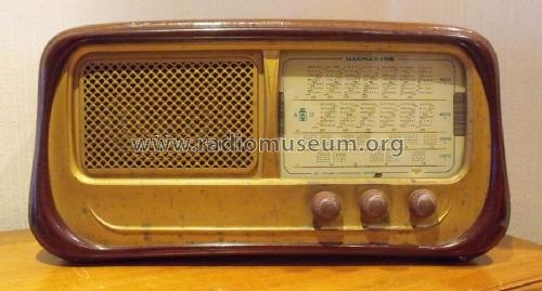
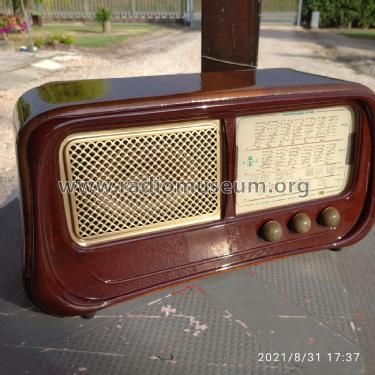
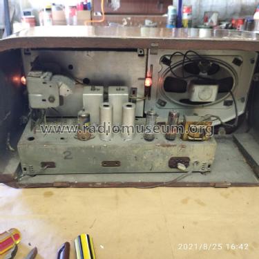
Foto per cortesia di S.Cavicchioni
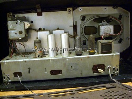
Foto per cortesia di S.Cavicchioni
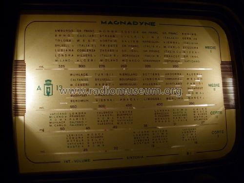
Foto per cortesia di S.Cavicchioni

Scansione originale della scala
post-restauro
Klicken Sie auf den Schaltplanausschnitt, um diesen kostenlos als Dokument anzufordern.
- Anzahl Röhren
- 5
- Hauptprinzip
- Superhet allgemein
- Wellenbereiche
- Wellen in den Bemerkungen.
- Betriebsart / Volt
- Wechselstromspeisung / 110; 125; 140; 160; 175; 230 Volt
- Lautsprecher
- Dynamischer LS, Prinzip (Edyn oder Pdyn) nicht gegeben.
- Material
- Gerät mit Holzgehäuse
- von Radiomuseum.org
- Modell: A13 - Magnadyne Radio; Torino
- Form
- Tischgerät-gross, - Querformat (breiter als hoch oder quadratisch).
- Abmessungen (BHT)
- 510 x 260 x 160 mm / 20.1 x 10.2 x 6.3 inch
- Bemerkung
- Sebbene lo schema indichi l'elenco valvole "ECH81 12P1 12DT1 50F2 35R2", sopra riportiamo quello più frequentemente rilevato nei modelli. Gamme d'onda: 2 medie e 2 corte.
Wave bands: 2x BC, 2x SW.
- Datenherkunft
- Guida Pratica Antique Radio V (2003)
- Autor
- Modellseite von Alessandro De Poi angelegt. Siehe bei "Änderungsvorschlag" für weitere Mitarbeit.
- Weitere Modelle
-
Hier finden Sie 357 Modelle, davon 276 mit Bildern und 258 mit Schaltbildern.
Alle gelisteten Radios usw. von Magnadyne Radio; Torino
Sammlungen
Das Modell befindet sich in den Sammlungen folgender Mitglieder.
Forumsbeiträge zum Modell: Magnadyne Radio;: A13
Threads: 1 | Posts: 4
Buongiorno a tutti - sono in possesso di una Magnadyne A13 (modello certo perchè riportato sulla scala parlante) che, a differenza di quanto si legge nella scheda di Radiomuseum monta le seguenti valvole : UCH42 - 12BA6 - 12AT6 - 50B5 - 35W4 , che sono poi anche le valvole montate sulla A15.
Poichè però nella scheda si legge che il modello A13 è stato suggerito da Alessandro De Poi ma è anche in possesso di Andrea Parolari, sarebbe interessante sapere dove è l'errore, onde eventualmente correggere la scheda stessa.
Attendo una risposta da qualcuno che ne sa qualcosa in più, o anche dal Socio Parolari, se può controllare le valvole dell'esemplare in suo possesso.
Saluti - Giuseppe Duello
Giuseppe Duello, 19.Jan.11