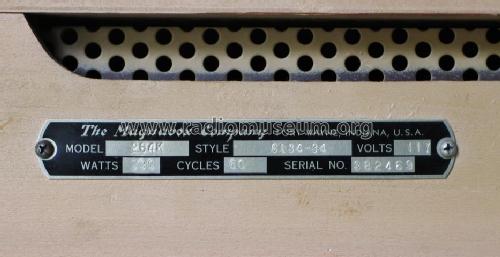
264K CR223E (radio) CT246B (TV) style C134-34
Magnavox Co., Commercial Wireless and Development Co.; San Francisco, later Fort Waye, IN
- Country
- United States of America (USA)
- Manufacturer / Brand
- Magnavox Co., Commercial Wireless and Development Co.; San Francisco, later Fort Waye, IN
- Year
- 1950 ?
- Category
- Television- and Radio Receiver, perh. also + Rec. etc. (TV Radio)
- Radiomuseum.org ID
- 193719


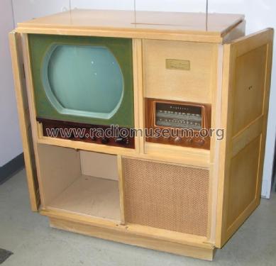
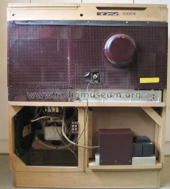
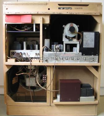
Back cover removed.
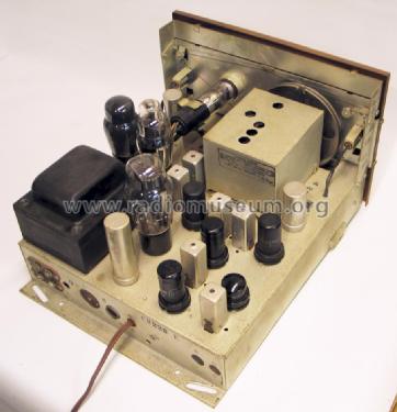
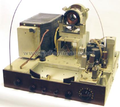
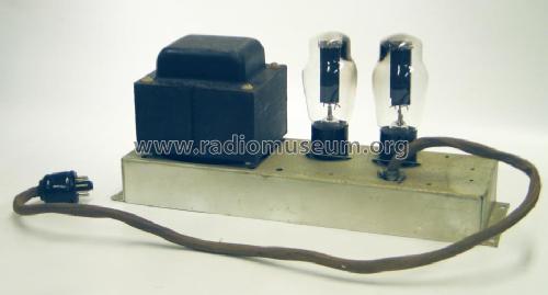
Radio and audio amplifier chassis
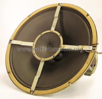
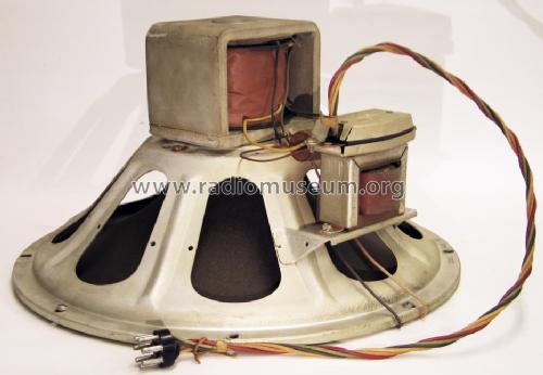
Rear of 15 inch speaker with field coil
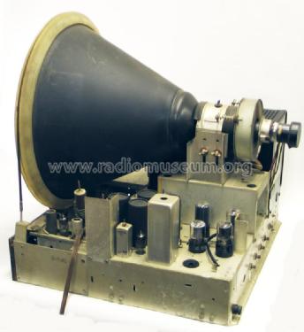
TV chassis front
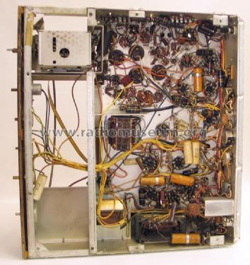
TV chassis bottom
TV power supply chassis
Click on the schematic thumbnail to request the schematic as a free document.
- Number of Tubes
- 39
- Valves / Tubes
- 6BA6 6BE6 6SG7 6SG7 6SH7 6H6 6SR7 6SN7GT 6L6G 6L6G 6U5G 5U4G 6AK5 6AG5 6AB4 6BA6 6BA6 6AU6 6AL5 6AG5 6AG5 6AG5 6AG5 6SN7GT 6V6GT 16EP4 6SN7GT 6SN7GT 6SN7GT 6V6GT 6SN7GT 6J5 6BG6G 6BG6G 1B3GT 1B3GT 6W4GT 5U4G 5U4G
- Number of Transistors
- Semiconductors
- 1N34A
- Main principle
- Superhet with RF-stage; ZF/IF 455/10700 21750 kHz
- Wave bands
- Wave Bands given in the notes.
- Details
- Changer (Record changer)
- Power type and voltage
- Alternating Current supply (AC) / 117 Volt
- Loudspeaker
- Electro Magnetic Dynamic LS (moving-coil with field excitation coil) / Ø 15 inch = 38.1 cm
- Power out
- 25 W (unknown quality)
- Material
- Wooden case
- from Radiomuseum.org
- Model: 264K CR223E CT246B [style C134-34] - Magnavox Co., Commercial
- Shape
- Console with any shape - in general
- Dimensions (WHD)
- 34.25 x 40 x 20.25 inch / 870 x 1016 x 514 mm
- Notes
-
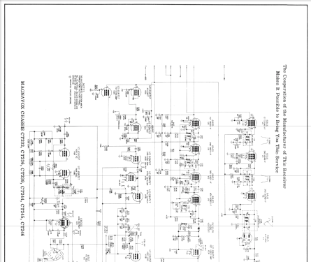
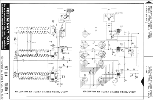
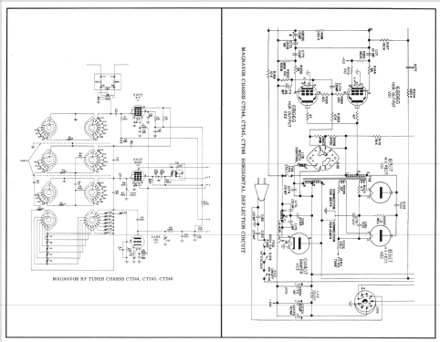
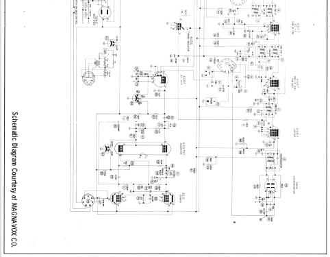
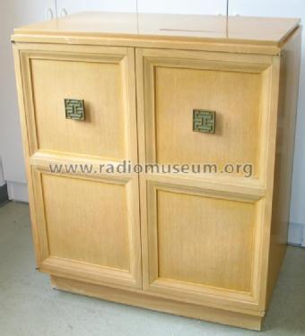
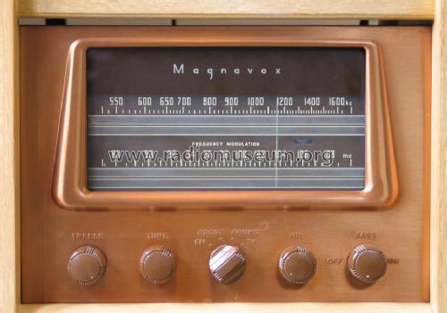
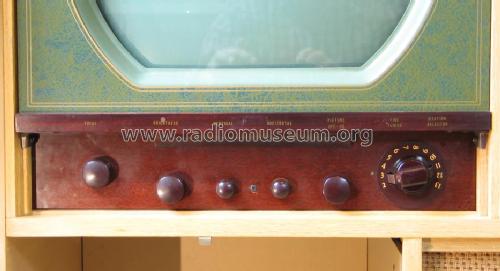
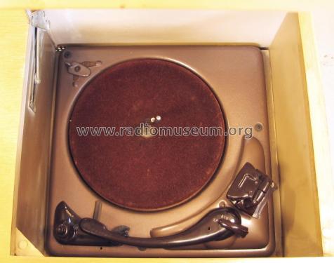
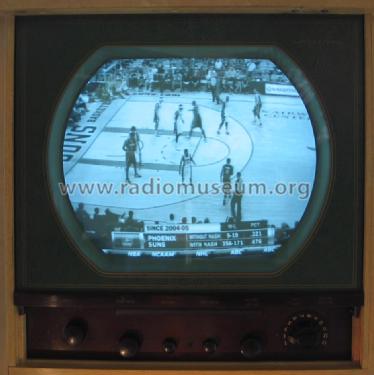
Magnavox model 264K is a blond wooden console combo with doors, incorporating an AM/FM radio, phonograph, and 16 inch TV. The audio amplifier is a high-end design for its day, with push-pull 6L6G output and a 15-inch coaxial speaker with a 4-inch tweeter using a capacitive crossover. The phonograph is an early 3-speed changer, with an unusual cartridge (not turnover type) that rocks between two positions to select between two styli on the bottom of the cartridge -- a "standard" stylus for 78 RPM records, and "LP" for 33 and 45 RPM records. The stylus is selected by a lever near the pivot of the tonearm which controls the tilt of the cartridge. The TV has a 12 channel standard US VHF tuner and uses a voltage doubler to generate a 14 kV high voltage supply for the 16EP4 metal CRT. Some units use a 16AP4 metal CRT, as documented in Sams and the tube placement chart in the set, which indicates only one 6BG6G horizontal output tube in that case. The video detector is a 1N34A germanium diode.
The date range was estimated by manufacturing date (29 December 1949) stamped on the chassis and the date on an original sales document (24 December 1950). The diode 1N34A was probably on the market in 1950 but was designed in 1949.
- Circuit diagram reference
- Photofact Folder, Howard W. SAMS
- Literature/Schematics (1)
- Sams set 93A folder 9 (TV) and set 436 Servicer (radio)
- Author
- Model page created by Thomas Albrecht. See "Data change" for further contributors.
- Other Models
-
Here you find 1082 models, 499 with images and 832 with schematics for wireless sets etc. In French: TSF for Télégraphie sans fil.
All listed radios etc. from Magnavox Co., Commercial Wireless and Development Co.; San Francisco, later Fort Waye, IN