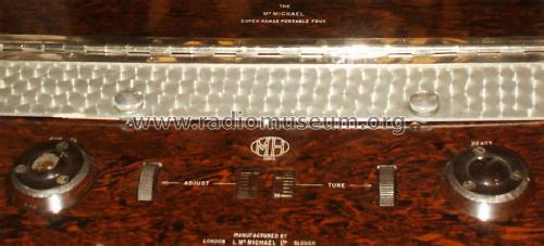
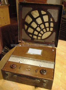
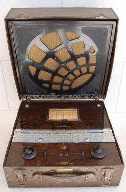
Super Range Portable four A (without tuning dial)
McMichael Radio Ltd.; Slough
- Pays
- Royaume Uni
- Fabricant / Marque
- McMichael Radio Ltd.; Slough
- Année
- 1929
- Catégorie
- Radio - ou tuner d'après la guerre 1939-45
- Radiomuseum.org ID
- 133868
-
- alternative name: McMichael, Leslie

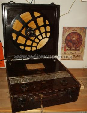
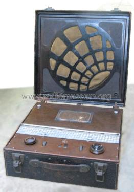
One knob and speaker not original
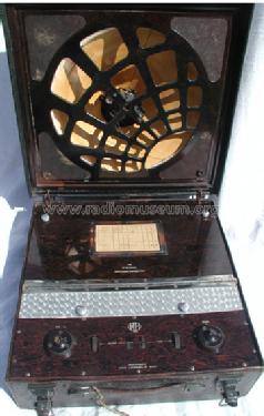
Holzkoffer, Lautsprecher im Deckel
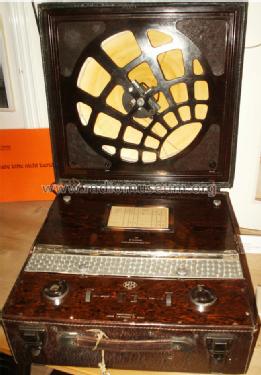
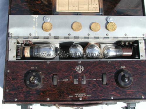
Die 2 äusseren Röhren sind zum aufklappen


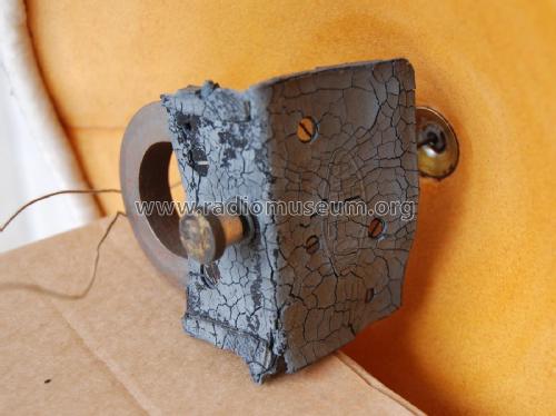
Installing valves (tubes)

Cliquez sur la vignette du schéma pour le demander en tant que document gratuit.
- No. de tubes
- 4
- Principe général
- Récepteur TRF - par réaction (régénératif); 2 Etage(s) BF; Réaction
- Circuits accordés
- 2 Circuits MA (AM)
- Gammes d'ondes
- PO et GO
- Tension / type courant
- Piles (rechargeables ou/et sèches) / 2 & 9 & 120 Volt
- Haut-parleur
- HP magnétique à haute qualité (aimant à 4 pôles) / Ø 30 cm = 11.8 inch
- Matière
- Cuir / canvas / plastique mais autre matériel en dessous!
- De Radiomuseum.org
- Modèle: Super Range Portable four A - McMichael Radio Ltd.; Slough
- Forme
- Portative > 20 cm (sans nécessité secteur)
- Dimensions (LHP)
- 394 x 229 x 406 mm / 15.5 x 9 x 16 inch
- Remarques
-
Volume control by filament rheostat on "SG" valve/tube (screen grid tuned RF preamp).
High impedance headphone jack socket and also Aerial & Earth sockets on speaker panel.
Batteries
Output valve grid bias via resistance between LT- and HT- rather than GB tap on battery is a later user/workshop modification. The original wiring is:
- LT 2V: red and black spade teminals for Accumulator. Probably 30AH. The Dry Batteries use 1/8" wander plugs.
- GB (grid Bias): GB+ (red), GB-1 (black,-1.5V), GB-2 (black -4.5V).Use a 9V GB pack 1.5V taps.
- HT (B+): HT+2 (red), HT+1 (red), HT- (black). . Probably a Winner 120 (taps for different screen voltages) with 60V for SG valve (tube).
Valve/Tube line up.
The early version of this model with wooden fret speaker grill rather than moulded Bakelite, it uses: PM12, PM1HF, PM1HL and PM2. Also claimed by one owner Bakelite panel.
Marconi 1931 catalogue: S22 H2 L2/B LP2
Mullard 1944 ist PM12, PM1HL, PM1HL and PM2A
Other owners report: PM12M rather than PM12, PM2HL or HL2 rather than HL210, PM1LF rather than HL210
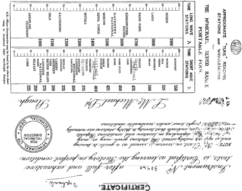
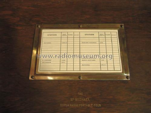
See SRPF Tuning scale for versions
- Poids net
- 10.7 kg / 23 lb 9.1 oz (23.568 lb)
- Auteur
- Modèle crée par Hans Martin Walchhofer. Voir les propositions de modification pour les contributeurs supplémentaires.
- D'autres Modèles
-
Vous pourrez trouver sous ce lien 183 modèles d'appareils, 123 avec des images et 120 avec des schémas.
Tous les appareils de McMichael Radio Ltd.; Slough
Collections
Le modèle Super Range Portable four fait partie des collections des membres suivants.
Musées
Le modèle Super Range Portable four peut être vu dans les musées suivants.
Contributions du forum pour ce modèle: McMichael Radio Ltd.: Super Range Portable four A
Discussions: 3 | Publications: 5
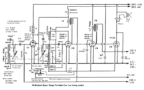
There are a few Schematics allegedly of this model available. All apart from a photo copy I have of a simplified schematic of Version "C" from McMichael seem to be either self drawn (only one found even close) or later models. Often the self drawn versions have added resistors so that the Grid Bias supplies and HT1 are not used allowing just a single 120V pack and 2V pack. Some of these modifications could of course date to 1940s, or be by the person drawing the modern schematic.
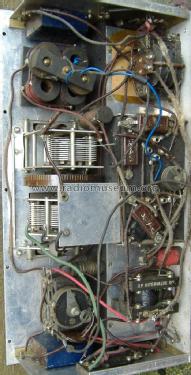
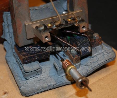
I have compared the actual McMichael Super Range Portable Four C [(with tuning dial)] schematic (uploaded) with my Model which I beleive to be unmodified (just a wire replaced before I received it). The McMichael Schematic doesn't show the "tone" control (likely because it's in the lid), Aerial/Earth connections, Phone jack or the L7. The McMichael Schematic also doesn't show that the 2nd RF tuning and regenerative feedback unit adjustment actually consists of six coils. I used the same designations but split as "a" and "b".
The McMichael Schematic also gives R2, a pair of wire wound resistors, a single designation, omits LT + power switch. R1 is actually two half travel Wire wound pots in parallel with three cams on a shaft to operate S1, S2 and S3. On MW all switches are closed and on LW only S2 is closed. No doubt S2 is in the middle to help with isolation between 1st RF tuning (Loop coils & C1) and 2nd RF tuning (Regeneration coils and C2)/
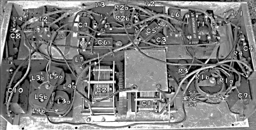
The correct Schematic for my version of the model has L7, a choke (coil) on V2 filament supply. On my version of the Schematic I have explained the aerial socket series capacitor (it's part of the connector) and shown the headphone jack switching which is obviously for high impedance (2K to 4K) headphones. The "Barrel" is +120V and "Tip" is V4 Anode. I have also uploaded a photo of the chassis with all component designations shown. These designations are not entirely logical to me, but copy the Super Range Portable Four C [(with tuning dial)] schematic from McMichael I uploaded. The additional changes are showing Aerial coupling capacitor, adding new designation L7 (missing entirely), S1, S2, S3, splitting R2, L3, L4 and L5.
L7 appears to be original on my version of the Model.
Michael Watterson, 29.Sep.13
This set uses three packs:
- Winner 120 style pack for 60V & 120V HT (USA "B")
- Winner 9 style GB (USA "C")
- 2V Lead Acid Accumulator, presumed to be wet (Gel is later 1930s) and presumed to be between 20AH and 75AH depending on space. The commonest size of the era is the about 35AH, for example the Ever Ready GZ 2V 36AH
Making a replica working Winner 120 is easy as dimensions are well known and the photos of old ones can be used to make panels to print. 80 off Alkaline AA at about €2 per 8 pack will give about the same capacity or a bit more than the original "B" cells used (2700mAH vs about 2500mAH for modern Zinc Carbon "B", = IEC R12) and 10 off 8 way AA holders allows the taps easily as well as fitting with plenty of space. This will have 5 to 10 years shelf life in cool conditions.
I made up a GB pack using 6 x Alkaline AA cells. But actually there is really no significant current draw, operational life is close to shelf life, so for authenticity I made a 2nd model. I bought 2 x 4.5V flashlight packs (old Ever Ready 1289, IEC 3R12, but actually Panasonic Brand). I popped of the plastic top and carefully pulled out the three cells without shorting. I added a card separator and joined the two sets, with 6 of the 7 sockets made from bent cut coffee tin strip soldered direct to top caps and the 0V socket soldered to side of cell case.

2V Lead Acid Accumulator
I had previously assured people that 2V Lead acid are still available. Well, up to a feeble 4AH is or a massive 200AH to 2000AH (UPS, Solar power systems etc). But not generally at 10AH to to 50AH.
So after testing on bench PSU I decided to use two sets of 3500mAH (3.5AH) NiMH giving 7AH total. This is more like a nominal 2.4V per two cells than 2V. Actually the Lead Acid is a nominal 2.1V. I tried 1N4007 as combiner diodes, but the voltage drop at 550mA load was close to 0.8V. A Pair of Schottky 1N5819 diodes as combiners gives just over 2.1V with full 550mA load and cells that are 1.35V each (near full charged) without a load.
I used an old 996 battery case to start with. Then I made this:

Glass jar with NiMH cells
Compare with Konrad Birkner's GZ 2V 36AH. The jar is glass and cost €2. The top is plastic and card. The handle is a wire coathanger. A fuse is sited where the valve/filler plug would be on a real one. The real cell is a bit taller and about 50% wider, but similar depth. The space left in the battery compartment by the two "Dry Cell" packs is pretty much what the 36AH Accumulator would need.
The 7AH is pathetic about 12 hours . but at least if the Radio is left on only about 1/30th to 1/40th of the HT pack is wasted. The HT might have lasted close to 400 hours and Accumulator (LT) maybe about 60 hours between charges. (One Tesco DAB radio from 2012 is only 6 hours!). The GB pack has shelf life. The Power switch only disconnects one wire of the Accumulator (LT).
Later 1930s Accumulators are Celluloid/Plastic case, the early 1920s are certainly glass. A more authentic style and size "pack" could be made from plastic sheet and probably accomodate 8 off "D" size 10AH NiMH for 35AH to 40AH using 4 combiner diodes. Two additional 1N4007 diodes allow charging which has a terminal voltage of close to 4V, But even with real Lead Acid Accumulator you shouldn't charge with radio on, or really without removing the pack. After all you can only charge it at the cycle shop :-) !

Appearance of battery compartment
The GB "Winner 9" should be further over, but the leads have probably got shorter every time the plugs resoldered!
Note: If the link of Winner 120 doesn't yet have instructions and plans check again later.
Edit: Photo of Accumulator updated. Good friend Albert gave me a better pair of terminals.
Michael Watterson, 28.Aug.13
I don't have a suitable Lead Acid Accumulator (yet!), so for LT filament I have two sets of two 3500mAH NiMH combined with 1N5818 "dropper diodes" which under load gives a reasonable voltage. Fully charged the NiMH terminals are about 1.4V (2.8V for two). The recommended end point is 1.1V (2.2V). On load the fully charged cells deliver slightly above 2.2V (they should not be connected to charger while in the Radio Set even if a Lead Acid).
Here is the Daytime Reception of LW on Youtube in the Midwest of Ireland of RTE1 and BBC R4. It also gets one French station quite readible on Daytime LW. I will add the MW at night as we only have one low power MW station at the other end of Ireland. Few radios pick that up here!
Replica Winner 120 (80 "budget" Alkaline AA cells) and 9V GB (6 x AA cells) packs are used.
Michael Watterson, 19.Aug.13