F.M. Converter CX-500 tubes 14F8, 35W4
Meck, John, Industries, Inc.; Plymouth (IN)
- Pays
- Etats-Unis
- Fabricant / Marque
- Meck, John, Industries, Inc.; Plymouth (IN)
- Année
- 1948 ?

- Catégorie
- Radio - ou tuner d'après la guerre 1939-45
- Radiomuseum.org ID
- 46945


Share Freely.


Share Freely.

Share Freely.
Cliquez sur la vignette du schéma pour le demander en tant que document gratuit.
- No. de tubes
- 2
- Principe général
- Principe spécial; FI/IF 23250 kHz; Superréaction
- Gammes d'ondes
- FM uniquement
- Tension / type courant
- Appareil tous courants (CA / CC) / 110-120 Volt
- Haut-parleur
- - Pour casque ou amplificateur BF
- Matière
- Bakélite ou plastique de type inconnu
- De Radiomuseum.org
- Modèle: F.M. Converter CX-500 [tubes 14F8, 35W4] - Meck, John, Industries, Inc.;
- Forme
- Modèle de table sans poussoirs, modèle cheminée
- Remarques
-
Frequency Range: FM-Band 88 to 108 Mc. Fremodyne reception principle.
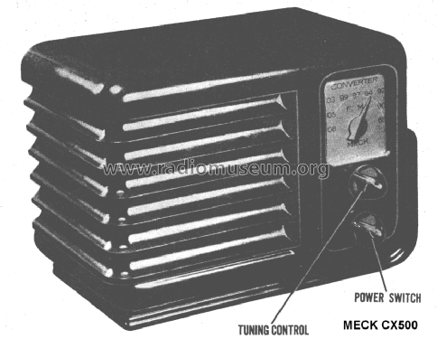
Production type of model CX500 F.M. Converter. With audio output transformer.See also these Meck CX500 models with IF frequency 21.75 MHz
- 2-tubes 7F8, 6H6
- 3-tubes 14F8, 12AT6, 35W4
- Source extérieure
- Ernst Erb
- Source du schéma
- Rider's Perpetual, Volume 19 = 1949 and before
- D'autres Modèles
-
Vous pourrez trouver sous ce lien 149 modèles d'appareils, 88 avec des images et 113 avec des schémas.
Tous les appareils de Meck, John, Industries, Inc.; Plymouth (IN)
Collections
Le modèle F.M. Converter fait partie des collections des membres suivants.
Contributions du forum pour ce modèle: Meck, John,: F.M. Converter CX-500
Discussions: 1 | Publications: 3
Fellow Radiophiles,
After a long wait for an automated search on ebay for a Fremodyne FM tuner or radio, I found this Meck FM Converter.
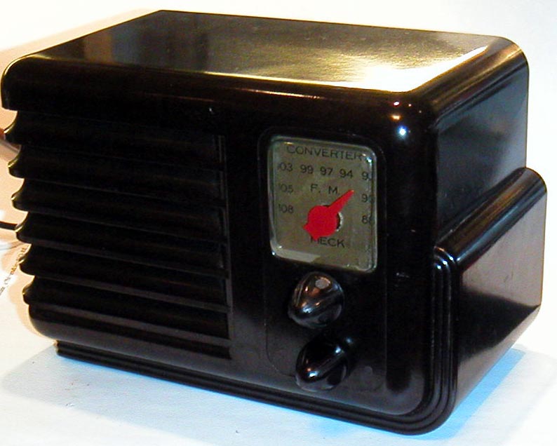
This FM converter might best be understood as an FM tuner because there is no output AM modulator to feed to an AM radio, but there is a standard transformer isolated audio output feeding an RCA plug.
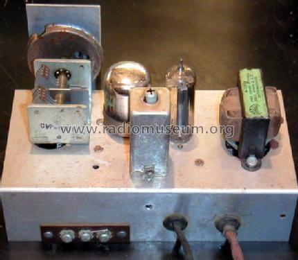
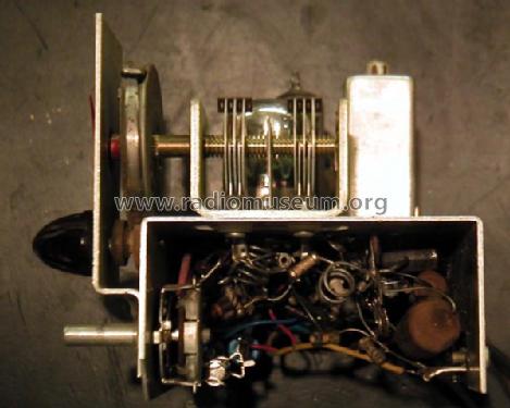
The construction of this single tube tuner is very simple. The handsome bakelite case has no mounting screws for chassis. The chassis is held in place by the two front knobs, one of which is for tuning and one is the power switch.
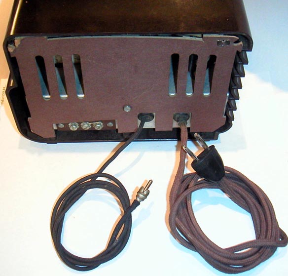 There are two options for the input antenna connection. One is via an external 300 Ohm twin lead, and the other uses the power cord as the antenna, by strapping two screw terminals together.
The power cord was still pliable, and in very good shape, but the built-in heater resistor was open in several places.
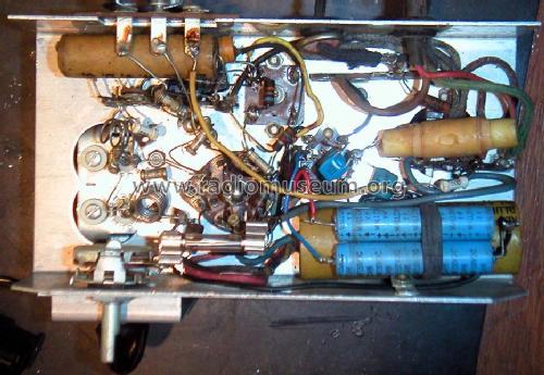
I replaced the 450 Ohm power cord resistor with 3.5uF of capacitance in series with the heaters.
I used five K5U capacitors in parallel, with 0.68uf capacitance, each. I pretested the capacitor voltage breakdown to withstand 600VDC with my Heathkit IT28 capacitor tester. (Ceramic capacitors often can widstand far more voltage than they are marketed for. Often, the rated voltage for high K ceramic capacitors simply means the highest voltage that the capacitance tolerance is maintained. Above the rated voltage, the capacitance drops out of spec.)
 The K5U capacitors appear as short stack of small blue capacitors soldered in parallel on the socket of the 35W4 power rectifier.
A 470k resistor should be added in parallel with the K5U capacitors to bleed stored charge.
I also added 0.2A slow blow fuse in series with the main power switch for added safety. This has become standard procedure for my radio restorations.
I left the original yellow dried-out supply bypass electrolytic in place, while adding two new electrolytic capacitors at the upper left, to replace the two dried up 40uF sections.
The 8uF electrolytic cap in the foreground had also dried up, so I added a 10uF 35V in parallel with this cap. It is located under the old cap.
Whenever possible, I like to leave the defective parts in place, and if leaky, I cut open one lead.
The yellow cylinder at the left is not a capacitor, but the RF transformer that couples the power cord to the front end, as an antenna, when terminals 2 and 3 of the antenna board in the foreground are shorted together.
Operation
The heart of this single tube FM tuner is the Fremodyne circuit. The Fremodyne is a variant of the Super-Regenerative FM detector. There are several references to Fremodyne operation within RMORG:
"Fremodyne" Superrgenerative Detector
FM Demodulators by Prof Dietmar Rudolph, in German, but could be read with Google-Translate.
 Summarizing the operational highlights, the 14F8 loktal dual triode uses one triode as a conventional local oscillator operating 23.25MHz above the incomming signal, and the second triode as mixer and Super-Regenerative detector at the fixed 23.25MHz IF frequency. Sometimes the Super-regenerative detection is described as accomplishing the function of IF amplifier and FM slope detector. This is true too.
The chassis is tied to one side of the power line via the power switch, but a 3X step-up audio isolation transformer, delivers audio safely to the RCA plug.
Modifications
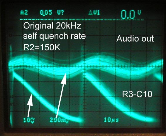 Originally, the self-quench frequency of the super-regenerative detector operated at 20kHz, and caused a lot of unpleasant frequency beats. The original detection slope was also too steep, and clipping distortion was heard on the louder passages.
The Rider alignment instructions describe R2=150k and C6=5nF as the primary determinants of the quench frequency, so I decided to experiment with R2 to increase the self-quench frequency to reduce beats with the FM stereo subcarrier.

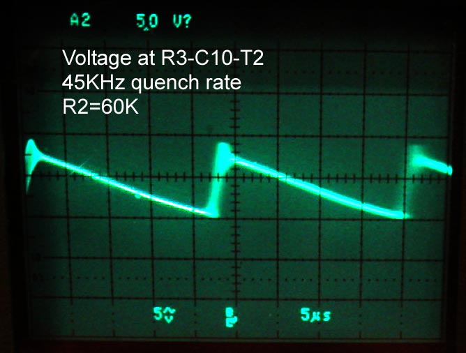
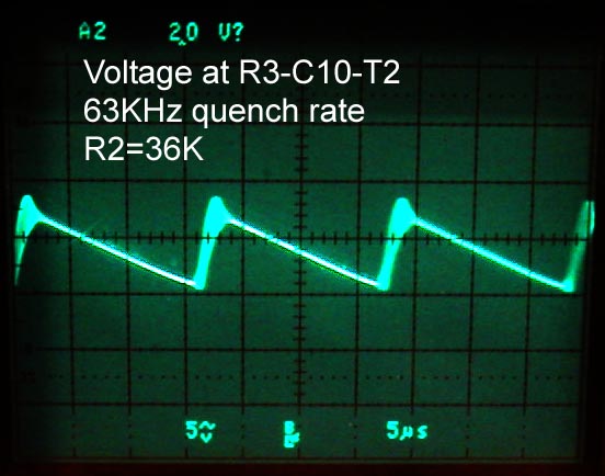
These three shots show the reduction in quench frequency, as I reduced R2 from the original 150k to 36k. I experimented with a 47k resistor in series with a 100k pot. I settled on the 45kHz quench rate, as it seemed to have relatively low beat energy with the 38kHz stereo sub-carrier.
One drawback of this method of increasing quench rate is that it also alters the mixer bias for the super-heterodyne conversion, this in turn, reduced the sensitivity (SNR) somewhat.
Another effect also reduced the amplitude of the output signal by about 5X, as can be seen by the reduced duty cycle modulation of the quench frequency in the three shots above.
The effect is that the higher bias level provided by R2 made the initial regeneration time constant of the 23.25Mhz oscilations much faster. This initial regeneration time constant sets the conversion from the FM slope of the tank circuit to the duty cycle of the cathode current. A fast time constant modulates the duty cycle less.
After I was done fiddling with the circuit, I tuned in the strongest local station and listened to it for one evening with the quench rate around 45kHz. The sound was surprisingly good.
When using the power cord as the antenna, I was able to get only two stations in the Boston-Massachusetts metropolitan area. My roof antenna pulled in another 8 stations.
Perhaps the original tuner configuration would have worked well with relatively low FM deviation, and without an FM subcarrier.
Comparing to other FM super-regenerative radios
When compared to my Hastings FM Jr, the Hastings showed better sensitivity. This could be due to the direct super-regenerative detection that the Hastings uses at the incomming carrier frequency. The super-heterodyne conversion loss in the Fremodyne seemed poorer, but that could be due to my increase in bias at R2.
From a circuit analsys point of view, I would expect higher performance from the Schaub-Pirol 56WU. The Pirol is also an FM superhet radio with super-regenerative detection, using just a dual triode for FM, like the Meck.
However, the Pirol makes much better used of the second triode, by running it as an additive self-oscillating converter with gain, instead of just running it as the fixed LO in the Meck. This type of front end is often quite sensitive when used with full super-heterodyne designs. I own a Grundig Concert-Boy 57 with this type of additive front end converter, and it is quite sensitive.
I don't own a Schaub-Pirol 56WU yet. Perhaps some day...
When searching RMORG for the topic of Super-Regeneration, use the German word "pendler", which means commuter, and refers to the quenching action. Then Google-Translate can be used to read the German language text.
Regards,
-Joe
Joe Sousa, 21.Dec.09