- Country
- United States of America (USA)
- Manufacturer / Brand
- Meissner Mfg. Div., Maguire Industries, Inc. (IL)
- Year
- 1951
- Category
- Broadcast Receiver - or past WW2 Tuner
- Radiomuseum.org ID
- 97375


Click on the schematic thumbnail to request the schematic as a free document.
- Number of Tubes
- 3
- Main principle
- TRF with regeneration
- Tuned circuits
- 1 AM circuit(s)
- Wave bands
- Wave Bands given in the notes.
- Power type and voltage
- AC/DC-set / 105-125 Volt
- Loudspeaker
- - For headphones or amp.
- Material
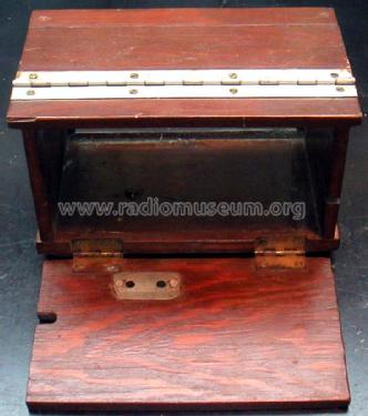
- Metal case
- from Radiomuseum.org
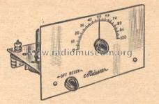
- Model: T3BK - Meissner Mfg. Div., Maguire
- Shape
- Chassis only or for «building in»
- Dimensions (WHD)
- 7.75 x 4.25 x 4.5 inch / 197 x 108 x 114 mm
- Notes
- Trainer receiver with extra plug-in coils for shortwave reception. One could order six different coils for the set. It normally came with the 2.8 and 8 MHz range coil with the basic kit (same as the 28K model).
- Price in first year of sale
- 12.00 $
- Literature/Schematics (1)
- 1951 Newark catalog Nº 51
- Author
- Model page created by Vitor Oliveira. See "Data change" for further contributors.
- Other Models
-
Here you find 76 models, 58 with images and 41 with schematics for wireless sets etc. In French: TSF for Télégraphie sans fil.
All listed radios etc. from Meissner Mfg. Div., Maguire Industries, Inc. (IL)
Forum contributions about this model: Meissner Mfg. Div.,: T3BK
Threads: 2 | Posts: 2
Fellow Radiophiles:
When I repair/restore a radio, I like to keep as many of the original components as possible in the radio. Recently, I started to replace bad or leaky paper capacitors in place.
The method is to cut one of the bad capacitor wires, and insert a small ceramic capacitor of the same value, and then short out the bad cap with a wire. This tends to preserve the apperance of the chassis and retains historical integrity in the set better than with hollowed out bad caps with new caps inside. These repairs can also be easily reversed.
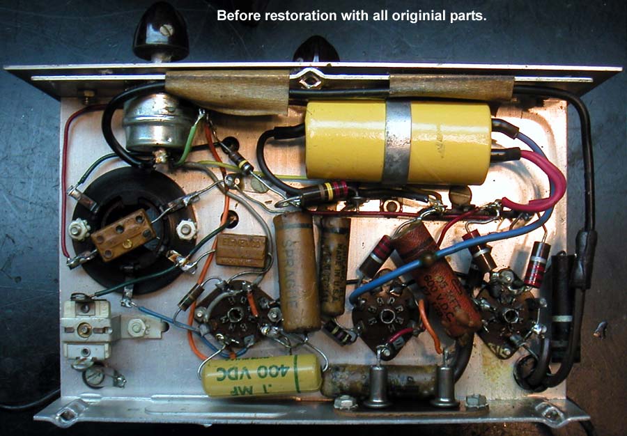

Another type of capacitor to consider as very small substitutes, are the modern multilayer chip capacitors. Yesterday I tested several values of COG capacitors between 0.1uF and 100pF that were rated for 50V operation, and I found much less than 1uA leakage at 400V. These caps were about 0.1" long, which is still easy to handle with tweazers. Leaded caps in this size range can also be used.
I plan to continue exploring the suitability of these capacitors for nearly invisible leaky paper cap repairs. I will apply higher voltage to find their breakdown voltage and leave the chip caps powered up over a long time at high voltages to identify any voltage stress effects. If I can manage elevated temperature for the long term cap test, I will do that too.
Regards,
-Joe
Joe Sousa, 14.Mar.10
Fellow radiophiles,
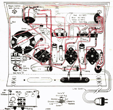
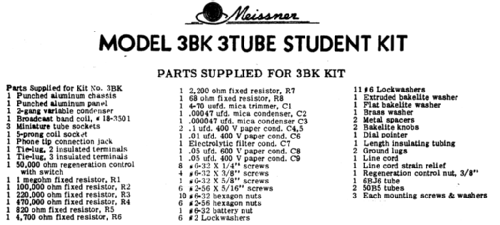
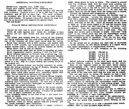
Ron Roscoe has kindly provided this scan of the sales description for two Meissner kits. Ron also provided the schematic and assembly info I just uploaded.
Thank you Ron.
Regards,
-Joe

Joe Sousa, 26.Jan.10