- Pays
- Etats-Unis
- Fabricant / Marque
- Meissner Mfg. Div., Maguire Industries, Inc. (IL)
- Année
- 1951
- Catégorie
- Radio - ou tuner d'après la guerre 1939-45
- Radiomuseum.org ID
- 97375


Cliquez sur la vignette du schéma pour le demander en tant que document gratuit.
- No. de tubes
- 3
- Principe général
- Récepteur TRF - par réaction (régénératif)
- Circuits accordés
- 1 Circuits MA (AM)
- Gammes d'ondes
- Bandes en notes
- Tension / type courant
- Appareil tous courants (CA / CC) / 105-125 Volt
- Haut-parleur
- - Pour casque ou amplificateur BF
- Matière
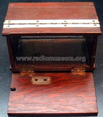
- Boitier métallique
- De Radiomuseum.org
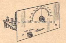
- Modèle: T3BK - Meissner Mfg. Div., Maguire
- Forme
- Chassis (pour intégration dans meuble)
- Dimensions (LHP)
- 7.75 x 4.25 x 4.5 inch / 197 x 108 x 114 mm
- Remarques
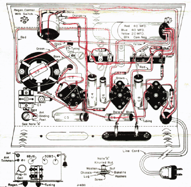
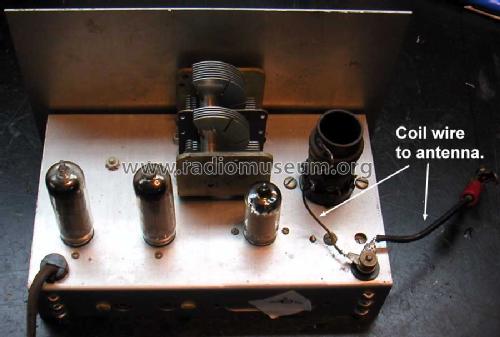
- Trainer receiver with extra plug-in coils for shortwave reception. One could order six different coils for the set. It normally came with the 2.8 and 8 MHz range coil with the basic kit (same as the 28K model).
- Prix de mise sur le marché
- 12.00 $
- Schémathèque (1)
- 1951 Newark catalog Nº 51
- Auteur
- Modèle crée par Vitor Oliveira. Voir les propositions de modification pour les contributeurs supplémentaires.
- D'autres Modèles
-
Vous pourrez trouver sous ce lien 76 modèles d'appareils, 58 avec des images et 41 avec des schémas.
Tous les appareils de Meissner Mfg. Div., Maguire Industries, Inc. (IL)
Contributions du forum pour ce modèle: Meissner Mfg. Div.,: T3BK
Discussions: 2 | Publications: 2
Fellow Radiophiles:
When I repair/restore a radio, I like to keep as many of the original components as possible in the radio. Recently, I started to replace bad or leaky paper capacitors in place.
The method is to cut one of the bad capacitor wires, and insert a small ceramic capacitor of the same value, and then short out the bad cap with a wire. This tends to preserve the apperance of the chassis and retains historical integrity in the set better than with hollowed out bad caps with new caps inside. These repairs can also be easily reversed.
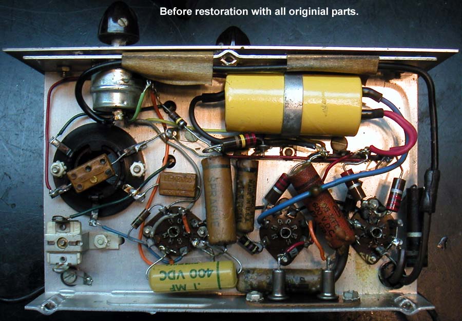

Another type of capacitor to consider as very small substitutes, are the modern multilayer chip capacitors. Yesterday I tested several values of COG capacitors between 0.1uF and 100pF that were rated for 50V operation, and I found much less than 1uA leakage at 400V. These caps were about 0.1" long, which is still easy to handle with tweazers. Leaded caps in this size range can also be used.
I plan to continue exploring the suitability of these capacitors for nearly invisible leaky paper cap repairs. I will apply higher voltage to find their breakdown voltage and leave the chip caps powered up over a long time at high voltages to identify any voltage stress effects. If I can manage elevated temperature for the long term cap test, I will do that too.
Regards,
-Joe
Joe Sousa, 14.Mar.10
Fellow radiophiles,
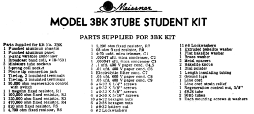
Ron Roscoe has kindly provided this scan of the sales description for two Meissner kits. Ron also provided the schematic and assembly info I just uploaded.
Thank you Ron.
Regards,
-Joe

Joe Sousa, 26.Jan.10