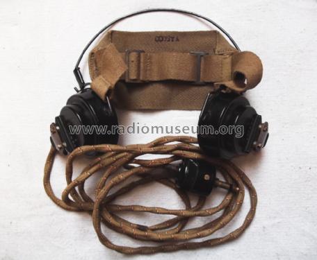
Headphones DLR No.5
MILITARY U.K. (different makers for same model)
- Country
- Great Britain (UK)
- Manufacturer / Brand
- MILITARY U.K. (different makers for same model)
- Year
- 1943 ?
- Category
- Loudspeaker, headphone or earphone
- Radiomuseum.org ID
- 204468
- Wave bands
- - without
- Power type and voltage
- No Power needed
- Loudspeaker
- - Is a Headphone or Earphone
- Material
- Bakelite case
- from Radiomuseum.org
- Model: Headphones DLR No.5 - MILITARY U.K. different makers
- Dimensions (WHD)
- 230 x 170 x 65 mm / 9.1 x 6.7 x 2.6 inch
- Notes
-
"Sound powered" or balanced armature type headphones. Medium Impedance, about 500 Ohms at 1kHz. See also DLR-1 and DLR-2 and the article for DLR-5 about rewinding. There are some other brands and US made balanced armature type headphones like the US Navy WWII (WW2) Deck Talker Headset Type R17T23.
DLR-5 hat einen verstellbarer Leinenstoffbügel.
- Net weight (2.2 lb = 1 kg)
- 0.450 kg / 0 lb 15.9 oz (0.991 lb)
- Author
- Model page created by Siegmar Mey. See "Data change" for further contributors.
- Other Models
-
Here you find 146 models, 114 with images and 48 with schematics for wireless sets etc. In French: TSF for Télégraphie sans fil.
All listed radios etc. from MILITARY U.K. (different makers for same model)
Collections
The model Headphones is part of the collections of the following members.
Forum contributions about this model: MILITARY U.K.: Headphones DLR No.5
Threads: 2 | Posts: 6
REWINDING THE DLR-5
To
HIBAPHONE
(High-Impedance-Balanced-Armature Phone)
written by By Dejan Momirov for radiomuseum.org
I wrote this article some years ago. In the meantime I got better testing instrumentation and re-checked the phones. Here is my article, with modified test results.
The article is a description of the procedure I performed trying to make a high-impedance-high-sensitivity earphone set. The idea was to combine the advantages of high impedance with the high sensitivity of a balanced-armature construction. I was more than satisfied with the results and would like to share my experience.
I’ve got several DLR-5 earphones and I decided to rewind the spools of one pair.
I first tested their characteristics and here they are:
DC-resistance..............................53 Oh
AC-impedance at 1 kHz............758 Ohms
Threshold at 1 kHz............... 1,268 picoW
Sensitivity............................ 88,97 dB/mW
It wasn’t easy at all, but I am sure, with some patience and enthusiasm, you can also do this.
Before you start, keep in mind:
Don’t rush, take your time!
Don’t panic if something goes wrong! Almost everything is reparable (see also the section troubleshooting).
Keep dust and small particles away.
Control every step done
Never de-solder and solder the coil contacts with the permanent magnet in place.
Use magnifying goggles.
Part 1 – Disassembling the Element
Fig.1 The front and rear of the original DLR-5 earpiece, in- and outside the housing.

When taking the element out, in such a small space and near the magnet, it is better to unscrew the contact screws first and than desolder the leads
After loosening the three screws on the top, first remove the magnet and then the upper plate of the magnet unit. It is very difficult to work within the strong magnetic field and there is the risk of damaging the armature.
Pull the leads out of the eyelet of the lead holder. Do not desolder the leads from the coil yet! The ends are wound around the coil contact plate.
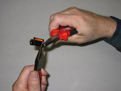
Unscrew the tiny nut from the drive rod using fine but strong forceps like those shown at
Fig. 2. (Bent microsurgical or the depilation forceps).

Remove the coil, with the reed still inside, straight upwards, to avoid damaging the drive rod.
Bottom plate of the magnet unit has to be removed only to be cleaned of the hardened varnish or dirt. Cleaning is important because varnish can later interfere with the reassembling the coil, damaging or breaking the wire and dirt particles may fall into the diaphragm space or between the armature and the coil.
Leave the diaphragm, drive rod and the second nut in place. Try not to touch the lower nut because it determines the central position of the armature.
All parts are shown at fig. 3.

Important: The two tiny "U”-shaped parts, marked with the arrows at the photograph (fig 3), are the only two fixation points of the reed; they also determine the distance between back end of the reed and the poles of the magnet unit. Remember the position of the two pieces before removing the reed from the coil form and don’t lose them!
Part 2 –Preparing the Coil Form
At the coil form, you see two contact-plates, each with lead-wire contact and coil-wire contact.
Bend them straight or a few degrees further as shown at fig. 4, using two pairs of pliers.
Don’t hold the coil form, it can break by bending!
Now remove the original wire (You may keep it, just in case you decide to undo everything) and clean the coil of varnish. Also, clean the soldering points.
Remove the isolation from the contact plates and polish both the plates and the edges of the coil form using fine sand-paper (# 360 or higher). The complete inner surface should be smooth and without any obstacles, otherwise it could catch and break the delicate thin wire later.
Fig.5 shows the form ready for winding. I used a piece of (lollipop) plastic tubing.

Part 3 – The Wire
The idea of the whole project was to get higher impedance, i.e as many turns as possible. To achieve that, you need the thinnest wire you can get and maximum space for it.
The wire I used was enamel coated 0.05 mm from a reed-relay activating coil. Another way is to order it via Internet by CONRAD, order nr. 60 75 09-06. One spool (cc 1500 m) is more then enough for the pair of phones. However, the wire must be solderable. The wires are shown at fig. 6. Available space is limited by the mounting rods, as shown at fig. 7. You can not stuff the whole form because of the clearance of 18 mm between the two mounting rods. The drawing also shows how to bend the contacts from their original position marked "1", to the temporary winding position marked "2". After winding, bend them back to the position "1". See also fig. 4! The available wire-space is marked "3".


Part 4 – Winding
The real work and excitement begins when everything is ready!
I have recently got a winding device for old 8mm movie films, shown at fig. 8.

You can also use a hand-drill fixed in the claws, as I did for years (fig. 9).

It is very important to centre the form perfectly; otherwise the windings can escape over the form edge.
Apart from wearing magnifying goggles, do have a bright spot light and put a white paper under the coil and the wire. It is important to see the wire and how you feed it. You can see better by looking with one eye only!
Choose the direction of winding so that the wire comes from upside the coil. The take-of-spool must also spin smoothly, without any resistance. Lead the wire and organise it within the coil with your left hand rested on a comfortable height; keeping it under a slight tension. See fig 8. Try to organise the windings as well as possible. Don’t make criss-cross, it takes unnecessary space. First try a few layers to get some experience and to feel the maximal tension in order not to break the wire. Than cut a few small strips of adhesive tape. You shall need them to fix the wire at the coil, in case you have to take a break for any reason (left hand cramp, coffee…)
Secure the start by making a threefold loop of 4-5 cm and twist it. Bend it around the soldering contact (do not cut it!), make the first few turns with such strengthened twisted part and then continue with single wire layers. Do the same at the end!
If you do not have automatic counter, mark at the paper every 100 turns. You will later want to know how many turns you have put into the coil. The total number of wire turns can be calculated by multiplying the number of drill-handle turns with the turn-ratio.
After finishing the winding, solder the ends and protect the windings with a 7mm wide strip of thin elastic adhesive tape or a thin layer of a transparent nail-polish.
Control the clearance for the two mounting rods: it should be 18 mm. Also, control with the Ohm-meter if the contacts are good. The DC resistance should be between 2000 to 2500 Ohms.
Part 5 – Reassembling the Element
Clean and check all parts prior to reassembling the unit in the opposite sequence. It means the bottom plate first. Slide the reed in the coil with small hole facing the contact-side. Than put the coil, with the reed inside and the two small fixation “U”-shaped parts in place, vertically onto the bottom plate so that the poles fit into the special grooves on the coil form. The drive-rod must pass through the small hole of the armature and the two fixation pieces must lie at the pole of the magnet unit bottom plate.
Now put back the upper nut of the drive rod and fasten the armature.
It is of crucial importance to check if the reed is free and at equal distance on both sides within the central slit of the coil form! If not – adjust distance using both nuts and tighten them. Remember that the vibrations of the armature-reed have to be transferred to the drive- rod and finally to the diaphragm. When you put back the upper plate, adjustment would be very difficult, if not impossible.
When everything is OK, put back the upper plate, so that the poles fit into the upper grooves of the coil form. Put the screws back, but don’t fasten them yet. First slide the magnet back and then fasten the screws.
Pull the leads through the eyelet of the lead-holder and check once again if the reed is at central position. If you look through the coil against the light, you should see equal spacing between the reed and the poles of the magnet unit. Also, make sure that the lead contacts are not touching the adjacent metal parts.
Now put the contact-screws back and fix the element into the housing.
Connect the flexible cable and the head-band and...Finally you’ve got it! (Fig 10)

Part 6 – Testing the Phones
To check the characteristics you may test the phones, or you can simply compare it with another set you have.
I tested the rewound headphone-set using the following instruments: signal-generator with IC: XR2206, digital storage oscilloscope OWON, PDS6062T and high-impedance (10MOhm) multimeter PROTEC, HC-5050E.
There are many procedures described on the Web to test the AC impedance and the sensitivity. I applied the one described by Dick Kleiert (www crystal-radio.eu/enluidsprekers.htm)
Here are the results:
- Windings per element..........................5300 + 5000
- Serial DC-set resistance.......................5180 Ohms
- AC Impedance at 1 kHz........................83,5 kOhms (set)
- Threshold at 1 kHz............................0,0108 picoW (set)
- Sensitivity.........................................109,67 dB/mW
The term “threshold” has to describe that I just was able to hear the 1 kHz signal in the compete silence. Of course, to understand the speech or music, you need more input energy.
Part 7 – Troubleshooting
In spite of all the attention and care something can always go wrong (Remember the Murphy’s law!). Here are some possible problems, and how you can solve them:
-… One of the two “U”- shaped reed-fixation part jumps off and you can not find it any more.
* Take a 0.2 mm thin sheet of a non-magnetic metal and cut a strip 2mm wide and 5 mm long. Bend it around 0.6 mm drill or similar (it is the thickness of the armature) in a U-shape.
- Coil form brakes.
* Cut a 3 x 8 mm piece of thin (0.15-0.2 mm) pertinaks or similar hard non- metallic material and glue the patch from the inside (wire-side) with cyan acryl glue. Of course, it reduces the number of turns.
- The wire breaks.
* Fix the last layer at the coil with a small drop of glue and twist both broken wire-ends together. Solder the joint, cut it off to the length of about 2 mm and continue winding. There is no need for any isolation (it occupies the precious space); just cover it with the next layer of wire.
- You lose the tiny nut of the drive-rod.
* Try to get one at the watch-maker’s or an optician’s, or in some hobby-shop. Have the element with the drive-rod with you to check the size.
It might be a good idea to have one extra (third) phone-element, just for the spare parts or to try again in case of serious problems!
Part 8 – Epilogue
I am well aware of the fact that my effort and the result are not the best for a serious DX-work, but it was fun to try something new. I might have made some mistakes, in the approach or testing. If anyone does or has done something similar, I would be grateful for any comments, corrections or confirmations. Also, if you want some more information, contact me at dejanmomirov[A*T]gmail.com
And finally,

fig. 11 shows my hobby-corner where everything happened.
Good luck,
Dejan
Dejan Momirov, 13.Apr.12
Hallo Sammler,
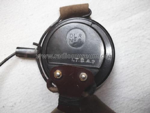
kann mir jemand etwas über den Hersteller dieses englischen Militarkopfhöhrers sagen.Die Beschriftung ist in der Anlage zu sehen. Aber evtl. ist bei Militärgeräten auch kein Hersteller zu finden. Der Stecker passt perfekt an Marconi CR und an Wavemeter Class D.
Viele Güße
S.Mey
Attachments
- Englischer Kopfhörer (128 KB)
- Englischer Kopfhörer (68 KB)
Siegmar Mey, 09.Oct.11