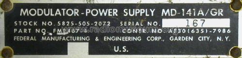
Modulator - Power Supply MD-141A/GR
MILITARY U.S. (different makers for same model)
- Country
- United States of America (USA)
- Manufacturer / Brand
- MILITARY U.S. (different makers for same model)
- Year
- 1959
- Category
- Military Equipment (not Re, Tr or RXT)
- Radiomuseum.org ID
- 206717


Click on the schematic thumbnail to request the schematic as a free document.
- Number of Tubes
- 14
- Main principle
- Transmitter
- Wave bands
- VHF incl. FM and/or UHF (see notes for details)
- Power type and voltage
- Alternating Current supply (AC) / 105-125, 210-250 Volt
- Loudspeaker
- - - No sound reproduction output.
- Material
- Metal case
- from Radiomuseum.org
- Model: Modulator - Power Supply MD-141A/GR - MILITARY U.S. different makers
- Shape
- Boatanchor (heavy military or commercial set >20 kg).
- Dimensions (WHD)
- 19 x 12.25 x 24 inch / 483 x 311 x 610 mm
- Notes
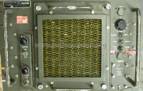
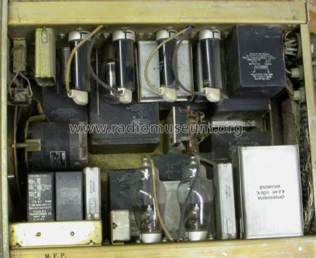
- The MD-141A/GR Modulator-Power Supply is the baseband unit of the AN/GRT-3 Radio Transmitter. It consumes 380 mains watts in either of two mains voltage ranges and is rated for continuous duty. It is capable of narrow-band modulation of 400 to 3000 Hz or broad-band modulation of 200 to 20,000 Hz both ranges being amplitude modulation with an input impedance of 50 or 600 ohms. The modulated B+ voltage is then fed to the system's transmitter unit, the Model T-282D/GR
- Net weight (2.2 lb = 1 kg)
- 170 lb (170 lb 0 oz) / 77.180 kg
- Source of data
- - - Data from my own collection
- Author
- Model page created by Hank Kaczmarski. See "Data change" for further contributors.
- Other Models
-
Here you find 408 models, 360 with images and 215 with schematics for wireless sets etc. In French: TSF for Télégraphie sans fil.
All listed radios etc. from MILITARY U.S. (different makers for same model)
Collections
The model Modulator - Power Supply is part of the collections of the following members.