Spectrum Analyzer TS-148/UP
MILITARY U.S. (different makers for same model)
- Produttore / Marca
- MILITARY U.S. (different makers for same model)
- Anno
- 1950 ??
- Categoria
- Apparato militare (senza Ri Tr o TRX)
- Radiomuseum.org ID
- 113014
Clicca sulla miniatura dello schema per richiederlo come documento gratuito.
- Numero di tubi
- 14
- Gamme d'onda
- Gamme d'onda nelle note.
- Tensioni di funzionamento
- Alimentazione a corrente alternata (CA) / 115 Volt
- Altoparlante
- - - Nessuna uscita audio.
- Materiali
- Mobile di metallo
- Radiomuseum.org
- Modello: Spectrum Analyzer TS-148/UP - MILITARY U.S. different makers
- Forma
- Soprammobile con qualsiasi forma (non saputo).
- Dimensioni (LxAxP)
- 330 x 235 x 400 mm / 13 x 9.3 x 15.7 inch
- Annotazioni
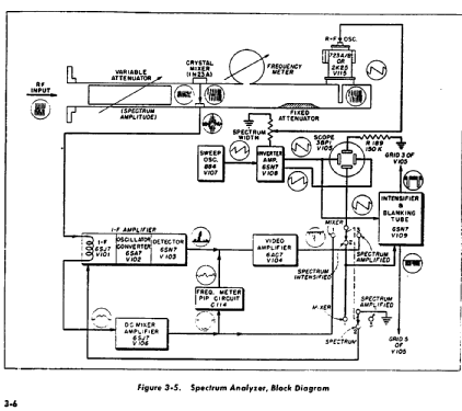
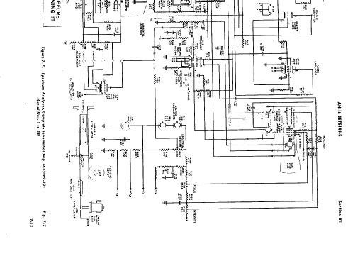
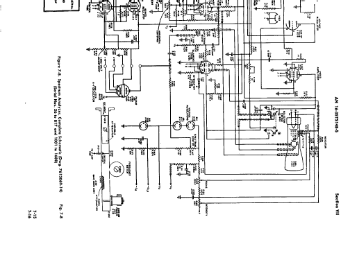
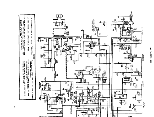
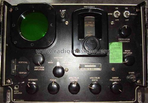
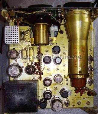
- This is the very early X band spectrum analyzer, designed and engineered during WWII. Just like most of the electronic equipment of its age, the TS-148/UP shows surprising simple and effective solutions. What is extraordinary in its design is that, just before, there was absolutely no practice about microwaves, with the sole exception of some university laboratories. The TS-148/UP was soon given, as standard test equipment, to each military department using X band radar equipment: for instance there is mention of this spectrum analyzer in the technical operation manual of the AN/MPG-1 radar, TM 11-1366, 15 March 1945. The excellence of its design can be fully understood considering that the unit in the picture, coming from the Italian Air Force, still carries the label with the date of its last calibration, 18/01/84: forty years of life should be well over the expectancy of its designers and it could still be used today! The equipment is very compact and sturdy. The principle is very simple, with a variable input attenuator, a resonating cavity preselector, a diode mixer and a klystron local oscillator. The repeller voltage of the klystron, and hence its output frequency, is modulated by a thyratron sawthoot generator, which also drives the horizontal deflection plates of the CRT. The coarse frequency adjustment is performed through the knob on the top right, which tunes the cavity of the reflex klystron. The frequency is read on the dial of the cavity resonator, from 8.430 to 9.660 MHz, with a resolution of 100 KHz. The equipment uses 18 tubes, including the CRT, and a silicon diode to do everything: the frequency conversion, the IF amplification and detection, the CRT deflection driving, up to the DC power supply.
- Peso netto
- 17 kg / 37 lb 7.1 oz (37.445 lb)
- Fonte dei dati
- - - Data from my own collection
- Bibliografia
- -- Original-techn. papers.
- Autore
- Modello inviato da Emilio Ciardiello. Utilizzare "Proponi modifica" per inviare ulteriori dati.
- Altri modelli
-
In questo link sono elencati 408 modelli, di cui 360 con immagini e 215 con schemi.
Elenco delle radio e altri apparecchi della MILITARY U.S. (different makers for same model)
Collezioni
Il modello Spectrum Analyzer fa parte delle collezioni dei seguenti membri.