High Fidelity Amplifier 20W
Mullard Wireless, London (see also Mullard Radio Valve)
- Country
- Great Britain (UK)
- Manufacturer / Brand
- Mullard Wireless, London (see also Mullard Radio Valve)
- Year
- 1958 ?
- Category
- Audio Amplifier or -mixer
- Radiomuseum.org ID
- 283569
From manufactures document.
Click on the schematic thumbnail to request the schematic as a free document.
- Number of Tubes
- 5
- Main principle
- Audio-Amplification
- Wave bands
- - without
- Power type and voltage
- Alternating Current supply (AC) / 200-250 Volt
- Loudspeaker
- - This model requires external speaker(s).
- Power out
- 20 W (undistorted)
- Material
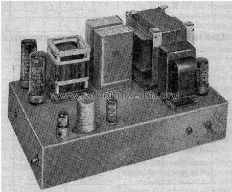
- Metal case
- from Radiomuseum.org
- Model: High Fidelity Amplifier 20W - Mullard Wireless, London see
- Shape
- Chassis only or for «building in»
- Notes
-
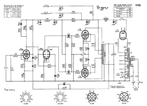
This amplifier is designed to give the highest standard of sound reproduction when used in association with a suitable pre-amplifier, a high-grade pick-up head and a good-quality loudspeaker system.
Two Mullard output pentodes, type EL34, rated at 25W anode dissipation, form the output stage of the circuit. These are connected in a push-pull arrangement with distributed loading, and give a reserve of output power of 20W with a level of harmonic distortion less than 0.05 %. The intermediate stage consists of a cathode-coupled, phase-splitting amplifier using the Mullard double triode, type ECC83. This stage is preceded by a high-gain voltage amplifier incorporating the Mullard low-noise pentode, type EF86. Direct coupling is used between the voltage amplifier and phase splitter to minimise low-frequency phase shifts.
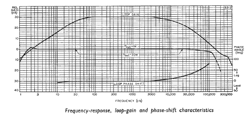
The main feedback loop includes the whole circuit, the feedback voltage being derived from the secondary winding of the output transformer and being injected in the cathode circuit of the EF86. The amount of feedback applied around the circuit is 30dB, but in spite of this high level, the stability of the circuit is good and the sensitivity is 220mV for the rated output power. The level of hum and noise is 89dB below the rated 20W.
The rectifier used in the power-supply stage is the Mullard full-wave rectifier, type GZ34. This provides sufficient current for the amplifier (about 145mA) and also for the pre-amplifier and f.m. radio tuner unit (about 35mA) being used with it
- Mentioned in
- - - Manufacturers Literature
- Author
- Model page created by Gary Cowans. See "Data change" for further contributors.
- Other Models
-
Here you find 144 models, 118 with images and 59 with schematics for wireless sets etc. In French: TSF for Télégraphie sans fil.
All listed radios etc. from Mullard Wireless, London (see also Mullard Radio Valve)