Naval Communications Receiver B40
Murphy Radio Ltd.; Welwyn Garden City
- Land
- Grossbritannien (UK)
- Hersteller / Marke
- Murphy Radio Ltd.; Welwyn Garden City
- Jahr
- 1953–1956
- Kategorie
- Kommerzieller Empfänger (auch Amateurbänder)
- Radiomuseum.org ID
- 76120


Variant C

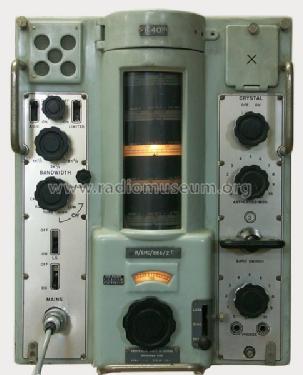
Variant C - front panel
Klicken Sie auf den Schaltplanausschnitt, um diesen kostenlos als Dokument anzufordern.
- Anzahl Röhren
- 14
- Röhren
- CV4014 CV2128 CV4009 CV4014 CV4015 CV4015 CV131 CV4007 CV4007 CV131 6BA6 0A2 CV493 CV493 CV2136
- Hauptprinzip
- Super mit HF-Vorstufe; ZF/IF 500 kHz; 2 NF-Stufe(n)
- Wellenbereiche
- Mittelwelle und mehr als 2 x Kurzwelle.
- Betriebsart / Volt
- Wechselstromspeisung / 115/230 Volt
- Lautsprecher
- Dynamischer LS, keine Erregerspule (permanentdynamisch) / Ø 7 cm = 2.8 inch
- Belastbarkeit / Leistung
- 2 W (Qualität unbekannt)
- Material
- Metallausführung
- von Radiomuseum.org
- Modell: Naval Communications Receiver B40 - Murphy Radio Ltd.; Welwyn
- Form
- Schweres Gerät für Militär oder Industrie (Boatanchor > 20 kg).
- Abmessungen (BHT)
- 13 x 19 x 16 inch / 330 x 483 x 406 mm
- Bemerkung
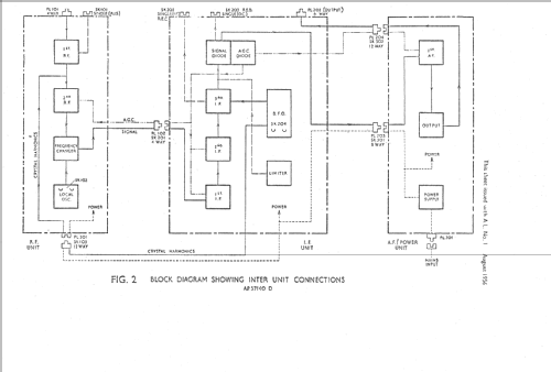
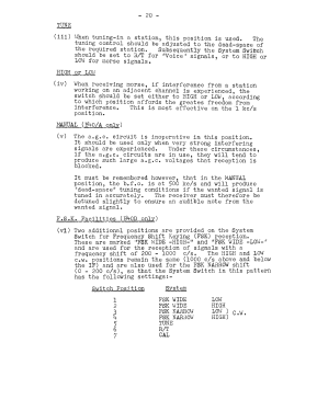
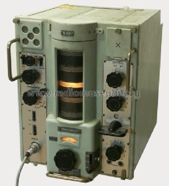
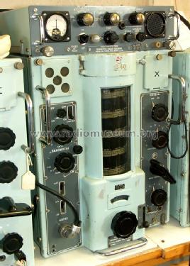
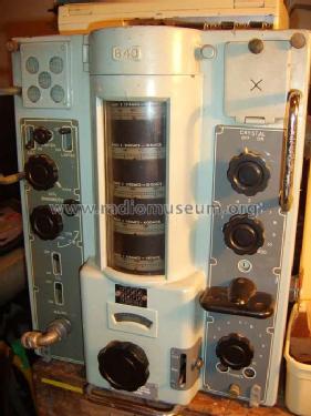
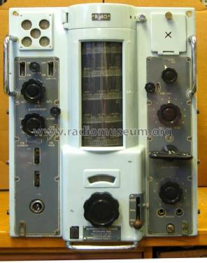
- The Murphy B40 Series of Naval Communications Receivers are receivers for shipboard use (British Navy, submarine), coverage 640 kHz to 30600 kHz in five ranges, IF-selectivity 1kHz/3kHz/8kHz, BFO. Also fix-frequency xtal-option. Model suffix A, B, C or D, the B40A, B40B, B40C and B40D, are some in details different variants. Also referred as "lighthouse- or tower-receiver".
- Nettogewicht
- 46 kg / 101 lb 5.1 oz (101.322 lb)
- Originalpreis
- 500.00 BP
- Literaturnachweis
- Shortwave Receivers - Past & Present (3rd ed.)
- Autor
- Modellseite von Alexander Küffer angelegt. Siehe bei "Änderungsvorschlag" für weitere Mitarbeit.
- Weitere Modelle
-
Hier finden Sie 367 Modelle, davon 301 mit Bildern und 234 mit Schaltbildern.
Alle gelisteten Radios usw. von Murphy Radio Ltd.; Welwyn Garden City
Sammlungen
Das Modell Naval Communications Receiver befindet sich in den Sammlungen folgender Mitglieder.
Forumsbeiträge zum Modell: Murphy Radio Ltd.;: Naval Communications Receiver B40
Threads: 2 | Posts: 2
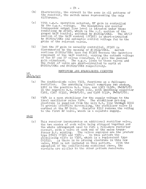
B40/A/B/C
B40/D (FSK Option)
In most cases, "Preferred" valves were fited by the manufacturer, and when replacements were necessary, "Reliable" types were used if available. Excerpt from original manual.
| Circuit Reference | Stage | CV no. | Equivalent |
| V101 | First RF | CV327 | EF52 |
| V102 | Second RF | CV303 | EF22 |
| V103 | Mixer | CV302 | ECH22 |
| V104 | Oscillator | CV327 | EF52 |
| V201/2/3 | 1st, 2nd, 3rd IF | CV303 | EF22 |
| V204 | Det. and AGC | CV140 | EB91, 6AL5, CV4025 |
| V205 | Noise Limiter | CV140 | EB91, 6AL5, CV4025 |
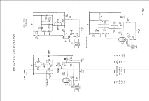
| V206 | BFO | CV303 | EF22 |
| V301 | AF Amp | CV303 | EF22 |
| V302 | Output | CV304 or CV2136 | EL22, 7C5 or 6BW6, 6061 |
| V303 | Rectifier | CV346 or CV1790 | EZ22 or 7Z4 |
| V304 | Stabiliser | CV287 | 150B3 |
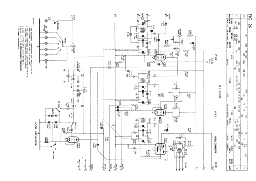
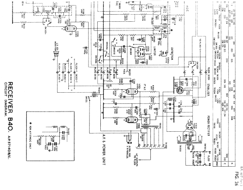
B40/D (FSK Option)
| Circuit Reference | Stage | "Preferred" CV no. |
Equivalent | "Reliable" CV no. |
Equivalent |
| V101 | First RF | CV138 | EF91 | CV4014 | 6064 |
| V102 | Second RF | CV454 | EF93 | CV4009 | 5749 |
| V103 | Mixer | CV2128 | ECH81 | ||
| V104 | Oscillator | CV138 | EF91 | CV4014 | 6064 |
| V201/2/3 | 1st, 2nd, 3rd IF | CV131 | EF92 | CV4015 | M8161 |
| V204 | Det. and AGC | CV140 | 6AL5 | CV4007 | 5726 |
| V205 | Noise Limiter | CV140 | 6AL5 | CV4007 | 5726 |
| V301 | AF Amp | CV454 | EF93 | CV4009 | 5749 |
| V302 | Output | CV2136 | 6BW6 | CV4043 | 6061 |
| V303 | Rectifier | CV493 | 6X4 | CV4005 | 6063 |
| V304 | Rectifier | CV493 | 6X4 | CV4005 | 6063 |
| V305 | Stabiliser | CV1832 | 0A2 |
In most cases, "Preferred" valves were fited by the manufacturer, and when replacements were necessary, "Reliable" types were used if available. Excerpt from original manual.
Martin Bösch, 03.Jun.07
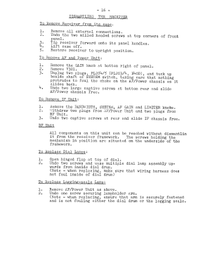
| Model No. / Admirality Pattern |
|
| B40 prototype 57140 |
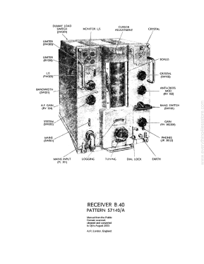
Typenumber engraved in flat cover above dial modes CAL, R/T, Tune system, CW high/low, listen through dial lock in left lower corner of main tuning knob. |
| B40A 57140A |
Typenumber above dial moulded in cast front panel modes CAL, R/T, Tune and CW high/low. Speaker switch lefthand under speaker grid. Physical changes in layout, mechanical changes to facilitate maintenance, substitution of improved components. |
| B40B 57140B |
Typeplate above dial screwed Re-designed tuning drive, addition of crystal filter in circuit, note filter deleted. AGC switch left under speaker and speaker switch fitted above mains switch. |
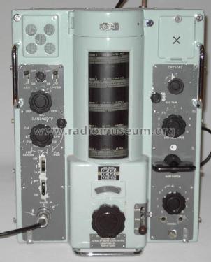
| B40C 57140C |
Typeplate above dial screwed, AGC switch left under speaker and speaker switch fitted above mains switch. RF assembly modified to allow Common Aerial working (use of several receivers on same antenna). |
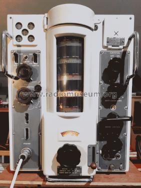
| B40D 57140D |
Typeplate above dial screwed Modes CAL, R/T, Tune, FSK narrow CW high/low and FSK wide high/low additional control for Oscillator Trim (fine tuning) left under CRYSTAL switch. Different valve layout (additional rectifier, EF9x series). |
| B41 | VLF variant Typenumber above dial moulded, lettering printed on faceplate. |
| B41 | VLF variant Typeplate above dial screwed, faceplate with lettering screwed on set. |
| 62B | VLF / HF general coverage variant. Typeplate screwed above dial, AGC switch underneath speaker grid, speaker switch above mains switch. |
Martin Bösch, 02.Jun.07