SW-3 and SW-5 Coil Data
National Company; Cambridge & Malden (MA)
- Produttore / Marca
- National Company; Cambridge & Malden (MA)
- Anno
- 1929–1946
- Categoria
- Parte di radio (ma non modulo a sè stante)
- Radiomuseum.org ID
- 286233
-
- alternative name: National Toy Co.
- Brand: Thrillbox


National SW3 coil number 63A (Bandspread)
Clicca sulla miniatura dello schema per richiederlo come documento gratuito.
- Gamme d'onda
- Gamme d'onda nelle note.
- Tensioni di funzionamento
- Alimentazione non richiesta
- Altoparlante
- - - Nessuna uscita audio.
- Materiali
- Speciale materiale, descritti nelle note.
- Radiomuseum.org
- Modello: SW-3 and SW-5 Coil Data - National Company; Cambridge &
- Forma
- Diverse forme (descritte nelle note).
- Dimensioni (LxAxP)
- 1.625 x 2.813 x 1.625 inch / 41 x 71 x 41 mm
- Annotazioni
-
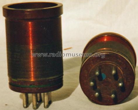
The National SW-3 and SW-5 Coils cover 0.09 MHz to 35.0 MHz, including bandspread coils for the 160, 80, 40, 20 and 10 meter amateur bands, There are three series of coils: the Series 10, 60 and 30 sets. Each band requires a coil for both the RF and Detector stages.
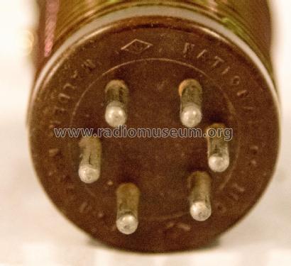
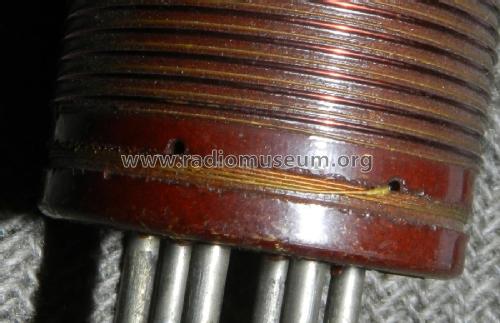
The coils are constructed of R-39, an ultra low-loss form material. The 6-pin base is unique to the National coils. It is not compatible with standard 6-pin tube bases or sockets.
Bandspread coils have grid cap leads, and the bandspread detector coils have a padding condenser. Note that there is no number 12A, 32A or 62A bandspread coils, since the 40 meter amateur band would fall in the range of the number 13, 33 and 63 coil sets.
Each coil set originally cost between $3.00 and $9.50, depending on coverage and series.
Series 10 Coils were used in both AC and DC receivers. The following National receivers use the series 10 coils: ACSW-5, ACSW-45, DCSW-34, DCSW-3 and original SW-3 Thrill Boxes. This would include any receivers from these series using type 24, 32, 34, 35, and 36 tubes in the RF and Detector stages. Some of the series 10 coils are marked with colored paint on the bottom for easy identification of the band.
Series 60 Coils were used in the ACSW-58 and ACSW-3 receivers utilizing either a type 58 or 6D6 in the Detector and RF stages. Some series 60 coils were engraved with their number on the bottom of the coil. (It is not clear when National started doing this.)
Series 30 Coils were used in the Universal SW-3 with either a 6J7 or 1N5 in the Detector and RF stages.
COIL RANGES:
#10 (Brown), 30 & 60 (9-15M)
#11 (Black), 31 & 61 (13.5-25M)
#12 (Red), 32 & 62 (23-41M)
#13 (White), 33 & 63 (40-70M)
#14 (Green), 34 & 64 (65-115M)
$15 (Blue), 35 & 65 (115-200M)
#16 (Orange), 36 & 66 (200-360M)
#17 (Yellow), 37 & 67 (350-550M)
#18 (Purple), 38 & 68 (500-850M)
#19, 39 & 69 (850-1200M)
#20, 40 & 70 (1200-1500 M)
#21, 41 & 71 (1500-2000m)
#22. 42 & 72 (2000-3000M)
#10A. 30A & 60A (10M Bandspread)
#11A, 31A & 61A (20M Bandspread)
#13A, 33A & 63A (40M Bandspread)
#14A, 34A & 64A (80M Bandspread)
#15A, 35A & 65A (160M Bandspread)
- Autore
- Modello inviato da Wayne Childress. Utilizzare "Proponi modifica" per inviare ulteriori dati.
- Altri modelli
-
In questo link sono elencati 446 modelli, di cui 285 con immagini e 189 con schemi.
Elenco delle radio e altri apparecchi della National Company; Cambridge & Malden (MA)
Collezioni
Il modello SW-3 and SW-5 Coil Data fa parte delle collezioni dei seguenti membri.