Empfänger-Prüfgenerator EP 104 BS
Neuwirth, Dipl.-Ing. H.-G.; Hemmingen /Hannover
- Country
- Germany
- Manufacturer / Brand
- Neuwirth, Dipl.-Ing. H.-G.; Hemmingen /Hannover
- Year
- 1960
- Category
- Service- or Lab Equipment
- Radiomuseum.org ID
- 173228


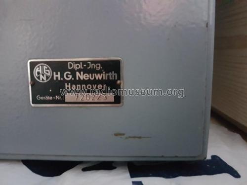

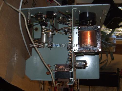
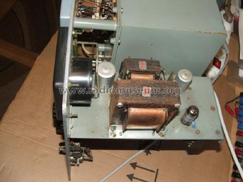

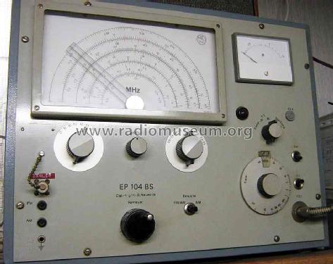
Foto Sammlertreffen
Click on the schematic thumbnail to request the schematic as a free document.
- Number of Tubes
- 6
- Number of Transistors
- Wave bands
- Wave Bands given in the notes.
- Power type and voltage
- Alternating Current supply (AC) / 220 Volt
- Loudspeaker
- - - No sound reproduction output.
- Material
- Metal case
- from Radiomuseum.org
- Model: Empfänger-Prüfgenerator EP 104 BS - Neuwirth, Dipl.-Ing. H.-G.;
- Shape
- Tablemodel, low profile (big size).
- Dimensions (WHD)
- 445 x 325 x 235 mm / 17.5 x 12.8 x 9.3 inch
- Notes
-
Frequenzbereiche AM:
0,14 - 0,420 MHz
0,40 - 0,525 MHz
0,48 - 1,800 MHz
1,80 - 6,000 MHz
6,00 - 22,00 MHzFrequenzbereiche FM/AM:
6,2 - 7,3 MHz
10 - 11,5 MHz
21 - 30,0 MHz
80 - 112 MHzAM: Modulationsgrad 30%/80%.
FM: Frequenzhub 15/25 kHz.
Ausgangsspannung: 0-30 mV.
Ausgangsleistung: 0-1,5 mW.Unterschiedliche Ausführung bei Frequenzbereichen und evtl. Netzspannungen je nach Gerätenummer.
- Source of data
- -- Original-techn. papers.
- Author
- Model page created by Karsten Bielfeldt. See "Data change" for further contributors.
- Other Models
-
Here you find 54 models, 45 with images and 20 with schematics for wireless sets etc. In French: TSF for Télégraphie sans fil.
All listed radios etc. from Neuwirth, Dipl.-Ing. H.-G.; Hemmingen /Hannover
Collections
The model Empfänger-Prüfgenerator is part of the collections of the following members.