Unknown communication receiver
NSF Nederlandsche Seintoestellen Fabriek, Hilversum
- País
- Holanda
- Fabricante / Marca
- NSF Nederlandsche Seintoestellen Fabriek, Hilversum
- Año
- 1922 ??
- Categoría
- Radio - o Sintonizador pasado WW2
- Radiomuseum.org ID
- 128142

Coil set of the radio.

Detail.
Haga clic en la miniatura esquemática para solicitarlo como documento gratuito.
- Numero de valvulas
- 1
- Válvulas
- C-I_Ideezet
- Principio principal
- RFS con reacción (regenerativo)
- Gama de ondas
- OM y OL
- Tensión de funcionamiento
- Baterías recargables o pilas / 4 & 45 Volt
- Altavoz
- - Este modelo usa amplificador externo de B.F.
- Material
- Madera con lámparas a la vista.
- de Radiomuseum.org
- Modelo: Unknown communication receiver - NSF Nederlandsche
- Forma
- Sobremesa, caja, normalmente con tapa (panel no inclinado).
- Ancho, altura, profundidad
- 470 x 375 x 335 mm / 18.5 x 14.8 x 13.2 inch
- Peso neto
- 12.7 kg / 27 lb 15.6 oz (27.974 lb)
- Procedencia de los datos
- - - Data from my own collection
- Autor
- Modelo creado por John Koster. Ver en "Modificar Ficha" los participantes posteriores.
- Otros modelos
-
Donde encontrará 160 modelos, 118 con imágenes y 85 con esquemas.
Ir al listado general de NSF Nederlandsche Seintoestellen Fabriek, Hilversum
Colecciones
El modelo Unknown communication receiver es parte de las colecciones de los siguientes miembros.
Contribuciones en el Foro acerca de este modelo: NSF Nederlandsche: Unknown communication receiver
Hilos: 1 | Mensajes: 1
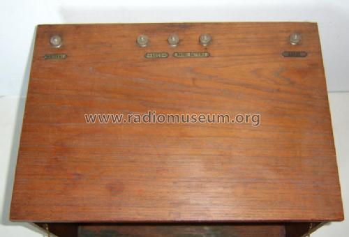
I recently bought this receiver, but I I am not really sure who the maker is. Does someone know more? This is a description of the radio:
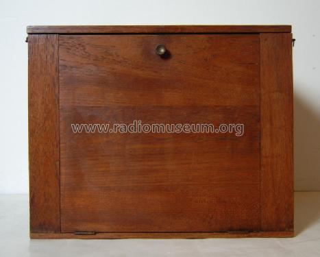
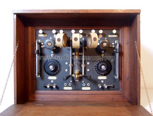
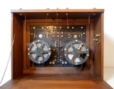
Both front and back have a hinged lid with chains. There are grips on the left and right hand side of the case. At the top of the receiver a row of binding posts for antenna, +30 volts, 0, +4 volts, and earth. On the upper side of the ebonite front there are binding posts that make it possible to connect an extra hf pre-amplifier or an lf amplifier. The radio is operated by a number of controls, situated at the front. Sliding resistors for filament and anode voltages are situated at the extreme left and right. In the middle the detector: a Philips C1 gas filled bright emitter. The tube is almost identical to the Philips Ideezet tube, issued in 1918. Behind this tube a four pin connection for a Philips D1 (a later addition?) is visible (see photo below). For tuning two variable condensers are available. Both can be operated by two bakelite knobs with a scale (0..100). The left one is used to tune the primary (antenna) circuit; the second one is used to tune the secondary circuit. Both circuits form a so called "band-pass filter". This construction offers better selectivity compared to a single circuit. Above the detector a threefold coil base is visible. Coil functions from left to right: primary coil, secondary coil, reaction coil. All coils are plug in types. A set of 11 coils is available. The coils measure 20,5 mm between the pins, a distance that deviates from Dutch standards. A handle with a remarkable long shaft and an extra bearing can be used to change the position the coils on the left and right. The coil on the left adjusts the coupling factor of the band-pass filter, the right coil adjusts the amount of reaction. Band width and selectivity both depend on this. With the coils available the receiver has a reach of 250 to 6000 meters. Between the coils and the sliding resistors two further knobs can be seen. The left one is used to switch the antenna circuit (serial/parallel). On the right a bipolar on/off switch that operates the filament voltage and the anode battery. Below the tuning knobs two short-circuit bridges to protect the variable condensers, as well as two sets of terminal sockets for a headset. The fixed condensers are by Dubilier Ltd. All materials, like the terminal sockets, clamps for the detector tube, the coil set, seem to be British (Marconi) and some also appear in the product catalogues of the Dutch NSF factory. The construction of the set suggests professional use. The radio could have been used near a transmitter. Receivers like this were used in shipping and in the army. It could also have been used as an experimental receiver for the Dutch (or Dutch East Indies) PTT.
 |
|
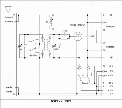
The circuit of the receiver is almost identical to this circuit, published by J. Corver in 1920. |
Anexos
- NL_NSF_onbekend_1922_front (78 KB)
- NL_NSF_onbekend_1922_detail (77 KB)
- NL_NSF_onbekend_1922_inside (78 KB)
John Koster, 22.Mar.08