Signal Generator & Tracer KB-141
Olson Radio Corporation, Olson Electronics Inc; Akron, OH
- Country
- United States of America (USA)
- Manufacturer / Brand
- Olson Radio Corporation, Olson Electronics Inc; Akron, OH
- Year
- 1959 ??
- Category
- Service- or Lab Equipment
- Radiomuseum.org ID
- 248994

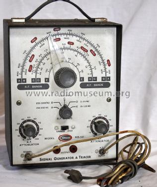
Picture courtesy of Tim Warneka
Click on the schematic thumbnail to request the schematic as a free document.
- Number of Tubes
- 4
- Wave bands
- Wave Bands given in the notes.
- Power type and voltage
- Alternating Current supply (AC) / 60 cycles, 120 Volt
- Loudspeaker
- Permanent Magnet Dynamic (PDyn) Loudspeaker (moving coil)
- Material
- Metal case
- from Radiomuseum.org
- Model: Signal Generator & Tracer KB-141 - Olson Radio Corporation, Olson
- Shape
- Tablemodel, with any shape - general.
- Notes
-
The Olson KB-141 is an AC operated, 4 tube combination signal generator and signal tracer. The signal generator can output either a modulated or unmodulated signal.
The RF Bands have the following frequency ranges:
Band A.............250 - 850kHz
Band B............850 - 3000kHz
Band C............3.0 - 11.0MHz
Band D............11 - 45MHz
Band E............35 - 120MHz
- Author
- Model page created by Tim Warneka. See "Data change" for further contributors.
- Other Models
-
Here you find 42 models, 38 with images and 5 with schematics for wireless sets etc. In French: TSF for Télégraphie sans fil.
All listed radios etc. from Olson Radio Corporation, Olson Electronics Inc; Akron, OH
Forum contributions about this model: Olson Radio: Signal Generator & Tracer KB-141
Threads: 1 | Posts: 1
If working on the 4 tube version of this signal generator / tracer, please note that terminals 6 and 7 in the schematic diagram are shown crossed over for the 5687 pre-amplifier tube. Pin 6 should the cathode and 7 is the grid. The tube pin voltage chart also incorrect. The same circuits are used for the Accurate Instruments Model 153 and the schematic diagram for that is correct.
Christopher Cusick, 04.Sep.18