Signal Generator & Tracer KB-141
Olson Radio Corporation, Olson Electronics Inc; Akron, OH
- Land
- USA
- Hersteller / Marke
- Olson Radio Corporation, Olson Electronics Inc; Akron, OH
- Jahr
- 1959 ??
- Kategorie
- Service- oder Labor-Ausrüstung
- Radiomuseum.org ID
- 248994

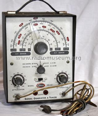
Picture courtesy of Tim Warneka
Klicken Sie auf den Schaltplanausschnitt, um diesen kostenlos als Dokument anzufordern.
- Anzahl Röhren
- 4
- Wellenbereiche
- Wellen in den Bemerkungen.
- Betriebsart / Volt
- Wechselstromspeisung / 60 cycles, 120 Volt
- Lautsprecher
- Dynamischer LS, keine Erregerspule (permanentdynamisch)
- Material
- Metallausführung
- von Radiomuseum.org
- Modell: Signal Generator & Tracer KB-141 - Olson Radio Corporation, Olson
- Form
- Tischmodell, Zusatz nicht bekannt - allgemein.
- Bemerkung
-
The Olson KB-141 is an AC operated, 4 tube combination signal generator and signal tracer. The signal generator can output either a modulated or unmodulated signal.
The RF Bands have the following frequency ranges:
Band A.............250 - 850kHz
Band B............850 - 3000kHz
Band C............3.0 - 11.0MHz
Band D............11 - 45MHz
Band E............35 - 120MHz
- Autor
- Modellseite von Tim Warneka angelegt. Siehe bei "Änderungsvorschlag" für weitere Mitarbeit.
- Weitere Modelle
-
Hier finden Sie 42 Modelle, davon 38 mit Bildern und 5 mit Schaltbildern.
Alle gelisteten Radios usw. von Olson Radio Corporation, Olson Electronics Inc; Akron, OH
Forumsbeiträge zum Modell: Olson Radio: Signal Generator & Tracer KB-141
Threads: 1 | Posts: 1
If working on the 4 tube version of this signal generator / tracer, please note that terminals 6 and 7 in the schematic diagram are shown crossed over for the 5687 pre-amplifier tube. Pin 6 should the cathode and 7 is the grid. The tube pin voltage chart also incorrect. The same circuits are used for the Accurate Instruments Model 153 and the schematic diagram for that is correct.
Christopher Cusick, 04.Sep.18