- Land
- Niederlande
- Hersteller / Marke
- Philips; Eindhoven (tubes international!); Miniwatt
- Jahr
- 1960 ?
- Kategorie
- Service- oder Labor-Ausrüstung
- Radiomuseum.org ID
- 184054


Typenschild
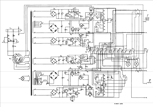
Klicken Sie auf den Schaltplanausschnitt, um diesen kostenlos als Dokument anzufordern.
- Anzahl Transistoren
- 16
- Wellenbereiche
- - ohne
- Betriebsart / Volt
- Wechselstromspeisung / 110; 125; 145; 200; 220; 245 Volt
- Lautsprecher
- - - Kein Ausgang für Schallwiedergabe.
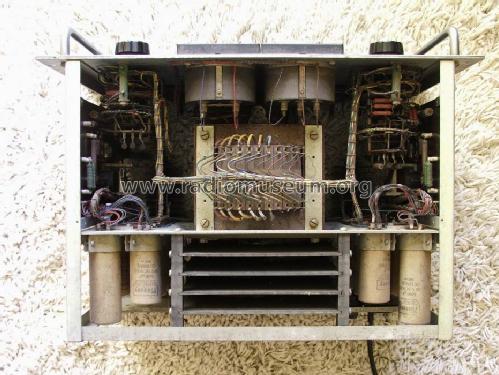
- Material
- Metallausführung
- von Radiomuseum.org
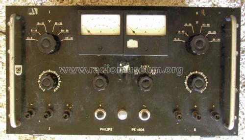
- Modell: PE4804 /01 - Philips; Eindhoven tubes
- Form
- Rack
- Abmessungen (BHT)
- 483 x 263 x 305 mm / 19 x 10.4 x 12 inch
- Bemerkung
- D.C. supply unit. Two galvanically separated outputs with independent adjustable and stabilized voltage. Both outputs can be connected in series or parallel, or operated independently. Adjustment of cut-off current only by means of pot (cabinet disassembly required).
Voltages: each 0.5 - 30 V (1 - 60 in series)
Currents: each max. 2 A (max. 4 A in parallel)
Stability at mains variations of ± 10 V from nominal, output voltage will not exceed ± 0.15% (@3 - 30V).
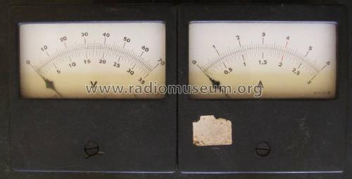
Moving coil voltmeter, two ranges 0 - 35 V and 0 - 70 V. Moving coil ammeter, two ranges 0 - 3 A and 0 - 6 A.
Transistors mentioned once per type: 4× 2N441, 2× OC92, 4× OC77, 2× OC30, 4× OC72.
- Nettogewicht
- 23 kg / 50 lb 10.6 oz (50.661 lb)
- Datenherkunft
- -- Original-techn. papers.
- Weitere Modelle
-
Hier finden Sie 5274 Modelle, davon 4421 mit Bildern und 3459 mit Schaltbildern.
Alle gelisteten Radios usw. von Philips; Eindhoven (tubes international!); Miniwatt