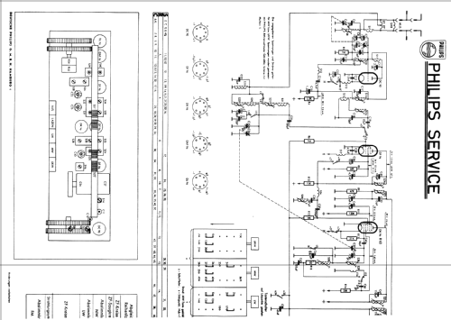
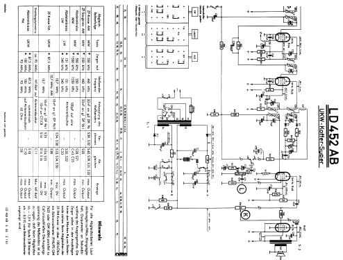
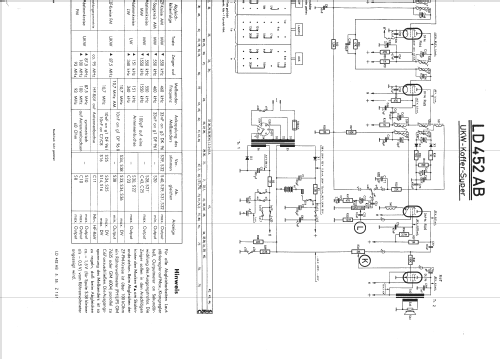
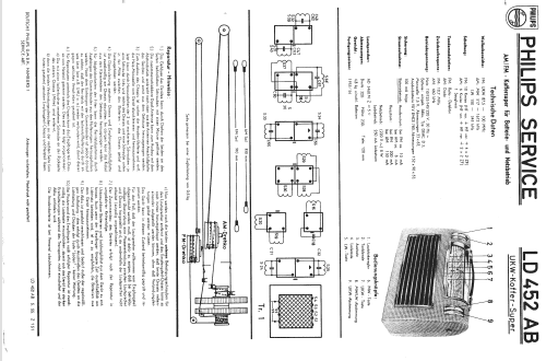
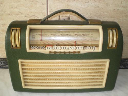
UKW-Koffersuper LD452AB
Philips Radios - Deutschland
- Country
- Germany
- Manufacturer / Brand
- Philips Radios - Deutschland
- Year
- 1955/1956
- Category
- Broadcast Receiver - or past WW2 Tuner
- Radiomuseum.org ID
- 7030
-
- Brand: Deutsche Philips-Ges.
Stabe G.

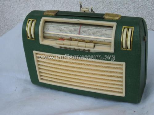
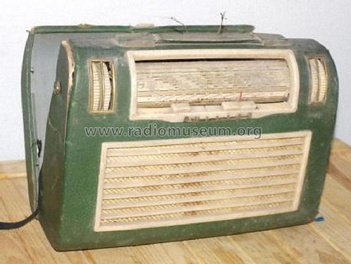
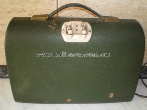
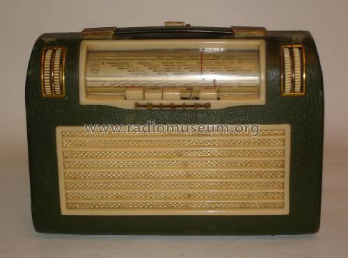
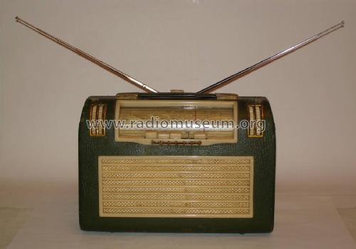
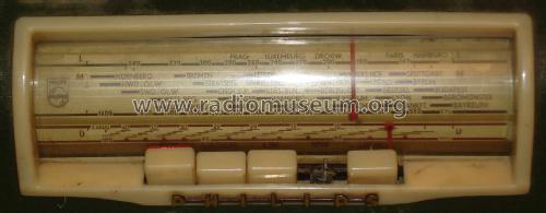
Philips LD452AB
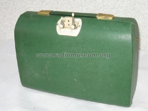
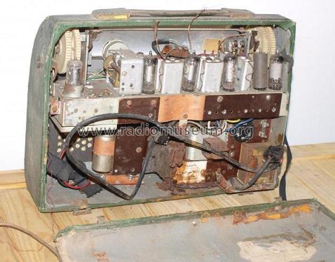
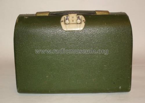
Philips LD452AB (Rückansicht)
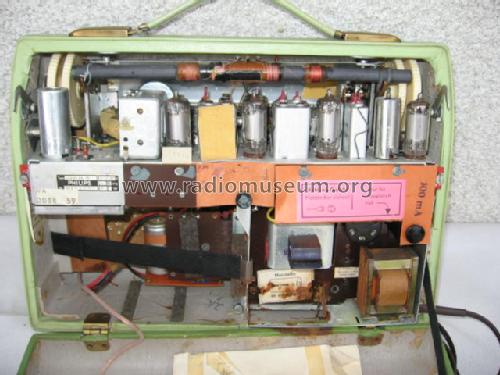
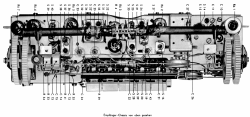
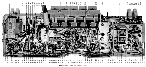
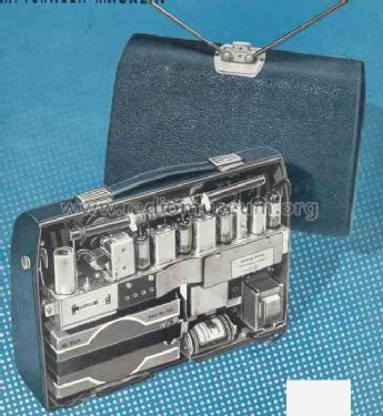
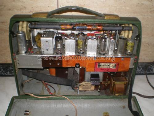
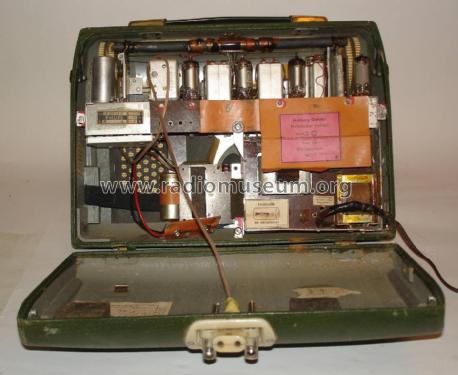
Philips LD452AB (Innenansicht)
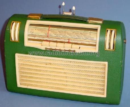
Philips UKW-Koffersuper LD452AB
Radio Magazin 3 ,März 1995
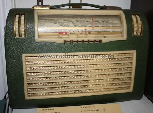
eine Drucktaste fehlt


Click on the schematic thumbnail to request the schematic as a free document.
- Number of Tubes
- 7
- Number of Transistors
- Semiconductors
- Tr.Gl.=Metal-rectif.
- Main principle
- Superhet with RF-stage; ZF/IF 460/10700 kHz; 2 AF stage(s)
- Tuned circuits
- 6 AM circuit(s) 10 FM circuit(s)
- Wave bands
- Broadcast, Long Wave and FM or UHF.
- Power type and voltage
- Line / Batteries (any type) / 110-220; 1,5 & 90 Volt
- Loudspeaker
- Permanent Magnet Dynamic (PDyn) Loudspeaker (moving coil) - elliptical
- Power out
- 0.2 W (unknown quality)
- Material
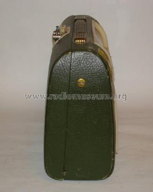
- Leather / canvas / plastic - over other material
- from Radiomuseum.org
- Model: UKW-Koffersuper LD452AB - Philips Radios - Deutschland
- Shape
- Portable set > 8 inch (also usable without mains)
- Dimensions (WHD)
- 300 x 220 x 120 mm / 11.8 x 8.7 x 4.7 inch
- Notes
- HF-Vorstufe für MW+LW.
Selbstschwingende additive Mischstufe für UKW.
FM-Demodulator mit 2 Germanium-Dioden.
Eingebaute DEAC-Zelle D3 (Heizakku).
- Net weight (2.2 lb = 1 kg)
- 4.8 kg / 10 lb 9.2 oz (10.573 lb)
- Price in first year of sale
- 282.00 DM
- Source of data
- Katalog Thiele,Helmstedt 1955/56 / Radiokatalog Band 1, Ernst Erb
- Mentioned in
- HdB d.Rdf-& Ferns-GrH 1955/56
- Literature/Schematics (1)
- -- Original-techn. papers.
- Other Models
-
Here you find 2548 models, 2260 with images and 1566 with schematics for wireless sets etc. In French: TSF for Télégraphie sans fil.
All listed radios etc. from Philips Radios - Deutschland
Collections
The model UKW-Koffersuper is part of the collections of the following members.
Forum contributions about this model: Philips Radios -: UKW-Koffersuper LD452AB
Threads: 4 | Posts: 16
Werte Kollegen,
habe dieses Radio in der Bucht ersteigert, allerdings ohne Teleskopantennen.
Würde Fotos von den Befestigungen der beiden Teleskopantennen benötigen um diese Teile so gut es geht nachzubauen.
Wer hat dieses Radio und könnte Fotos machen?
Mit bestem Dank im Voraus
D. Grötzer
Dietrich Grötzer, 21.Sep.17
The "ferrite rod" and coils was missing, but central connection strip/saddle remains.
Looking at rear, there are 3 connections:
a) is both connected S21 and S22
b) is other end of S21
c) is other end of S22
Which of S21 and S22 is LW and which is MW?
From rear on the three connections, left to right, which is a, b and c?
What is total inductance of S21, it is in two parts?
What is total inductance of S22, it is in two parts?
Is the spacing of the two parts of S21 to adjust inductance? Similarly for S22?
I obtained 200mm ferrite rod and glued on a 33mm section so the rod is 233mm and fits on bracket. It may of course not be same permability.
In the absence of other information I will try a few very old MW and LW transistor radio coils on the large ferrite rod.
Michael Watterson, 08.Jan.12
Die "Ferritstab" und Spulen fehlte, aber zentrale Steckerleiste / Sattel bleibt.
Mit Blick auf Rückseite befinden sich 3 Anschlüsse:
a) ist sowohl verbunden S21 und S22
b) ist anderen Ende der S21
c) ist anderen Ende der S22
Welche der S21 und S22 ist LW und die MW?
Von hinten auf die drei Verbindungen, von links nach rechts, die a, b und c?
Was ist insgesamt Induktivität der S21, ist es in zwei Teile?
Was ist insgesamt Induktivität der S22, ist es in zwei Teile?
Ist der Abstand der beiden Teile der S21 bis Induktivität einstellen? Ähnliches gilt für S22?
Ich erhielt 200mm Ferritstab und verklebt auf einem 33mm Abschnitt so wird der Stab 233mm und passt auf Bügel. Es kann natürlich nicht gleichzeitig permability werden.
In Ermangelung anderer Informationen, die ich noch ein paar sehr alte MW-und LW-Transistor-Radio Spulen auf dem großen Ferritstab versuchen
Michael Watterson, 08.Jan.12
Where exactly does the VHF aerial coax connect to on the Chassis? It's only connected to what used to be the telescopic aerials.
I presume my set is this set as the remaining part of valve layout label shows a DC90 in the first position instead of a DF97.
When you remove the Chassis from case there is a set of tags and a Resistor sized RF choke on the front of VHF tuning module. I presume this might be where it was pulled off?
Michael Watterson, 16.Dec.11