Multi-Signalgeber SIM212
Philips Radios - Deutschland
- Paese
- Germania
- Produttore / Marca
- Philips Radios - Deutschland
- Anno
- 1981/1982
- Categoria
- Strumento da laboratorio
- Radiomuseum.org ID
- 138919
-
- Brand: Deutsche Philips-Ges.


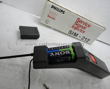

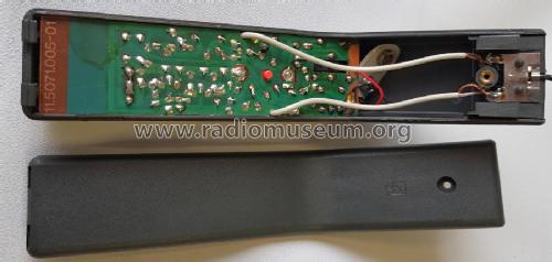
SIM212 Rear view

SIM212 PCB Top View

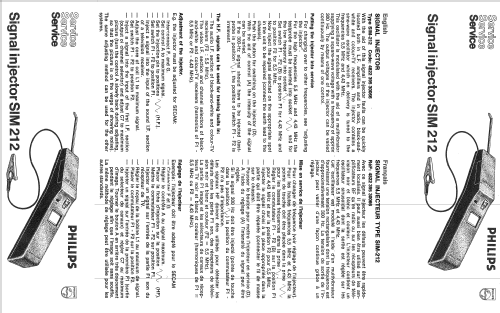
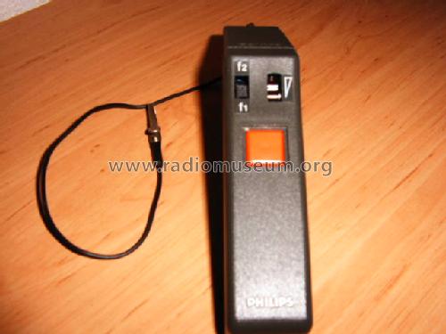
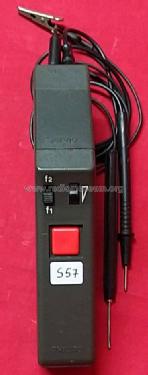
SIM212 Front View
Clicca sulla miniatura dello schema per richiederlo come documento gratuito.
- Numero di transistor
- 5
- Gamme d'onda
- - senza
- Tensioni di funzionamento
- Batterie a secco / 9 Volt
- Altoparlante
- - - Nessuna uscita audio.
- Materiali
- Plastica o bachelite
- Radiomuseum.org
- Modello: Multi-Signalgeber SIM212 - Philips Radios - Deutschland
- Dimensioni (LxAxP)
- 190 x 30 x 35 mm / 7.5 x 1.2 x 1.4 inch
- Annotazioni
-
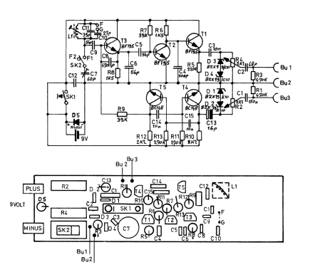
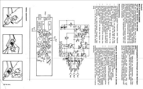
Handlicher Signalgenerator zur Fehlersuche in NF-Verstärkern, RF-, SW- und FFS-Geräten mit Sinusoszillator, 4,43/5,5 MHz umschaltbar. Modulation mit 300-Hz-Rechteckschwingung aus Multivibrator.
SlGNAL INJECTOR, Type SIM-212 Code: 4822 395 30066
Description:
With the aid of this signal injector faults can be quickly located both in L.F. amplifiers and in radio, black-and white and colour-TV receivers. The injector contains a sine-wave oscillator which on delivery is tuned to the frequencies 5.5 MHz and 4.43 MHz.
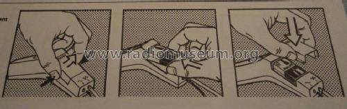
This oscillator is modulated with the aid of a multivibrator supplying a square-wave voltage with a frequency of approx. 300 Hz. The output voltages of the injector can be varied continuously by means of one control.Putting the injector into service
- For changing over to other frequencies, see " adjusting the injector".
- For the high frequencies 5.5 MHz and 4.43 MHz the test probe must be inserted into socket ∿∿ for the low frequency into socket ∿.
- Set switch F1 - F2 (B) to position F1 for 4.43 MHz and to position F2 for 5.5 MHz.
- Now inject the signal selected on the appropriate spot in the unit to be repaired (connect the earth lead to the chassis).
- Push the button for switching on the injector (D) .
- With the aid of control (A) the intensity of the signal can be varied.
- lf the 300-Hz signal should have to be injected (test probe in position ∿ ), the position of switch F1 - F2 is irrelevant.The H.F. signals can be used for tracing faults in:
- The audio I.F. section of black-and-white and colour-TV receivers (F2 : 5,5 MHz).
- The video I.F. section and channel selectors of black & white and colour-TV receivers (harmonics of F1 – 5.5 MHz or F2 – 4.43 MHz).Adjustment of the injector:
E.g. the injector must be adjusted for SECAM:
- lnterconnect F. and G.
- Set control A to maximum signal.
- Set the injection pin to positions ∿∿ (H.F.).
- Set switch F1 - F2 to position F1.
- Inject a signal into the input of the sound I.F. section of a television receiver.
- Adjust the care of coil L 1 to maximum signal.
- Set switch F1 - F2 to position F2.
- lnject a signal into the input of the first I.F. section (output of channel selector) and adjust C7 to maximum picture (turn the control A slowly back during adjusting, so that the picture is on the verge of showing noise).
The same adjusting method can be used for the other systems.
- Peso netto
- 0.2 kg / 0 lb 7 oz (0.441 lb)
- Fonte dei dati
- - - Manufacturers Literature
- Autore
- Modello inviato da un iscritto da D. Utilizzare "Proponi modifica" per inviare ulteriori dati.
- Altri modelli
-
In questo link sono elencati 2544 modelli, di cui 2257 con immagini e 1566 con schemi.
Elenco delle radio e altri apparecchi della Philips Radios - Deutschland
Collezioni
Il modello Multi-Signalgeber fa parte delle collezioni dei seguenti membri.