- Country
- United States of America (USA)
- Manufacturer / Brand
- Pilot Electric Mfg. Co. (Radio Corp.); Brooklyn (NY)
- Year
- 1940
- Category
- Broadcast Receiver - or past WW2 Tuner
- Radiomuseum.org ID
- 52017
-
- alternative name: Pilot Radio & Television || Pilot Radio and Tube || Pilot Radio Corporation
Click on the schematic thumbnail to request the schematic as a free document.
- Number of Tubes
- 10
- Number of Transistors
- Main principle
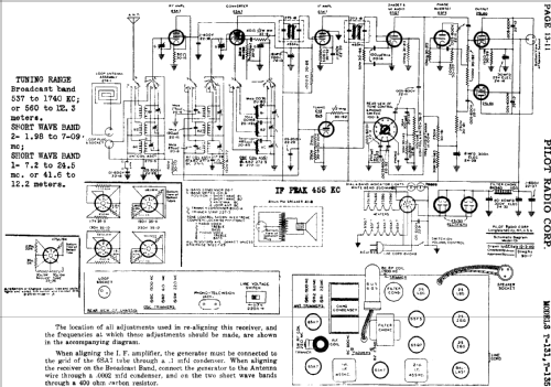
- Superhet with RF-stage; ZF/IF 455 kHz
- Tuned circuits
- 7 AM circuit(s)
- Wave bands
- Broadcast plus 2 Short Wave bands.
- Power type and voltage
- AC/DC-set
- Loudspeaker
- Permanent Magnet Dynamic (PDyn) Loudspeaker (moving coil) / Ø 8 inch = 20.3 cm
- from Radiomuseum.org
- Model: T-131 - Pilot Electric Mfg. Co. Radio
- Notes
- Different ballast tubes (35-9 to 35-12 or 35-26) are used for 117 V, 130 V, 150 V or 230 V mains supply; built-in loop antenna; tuning eye; push-pull af output stage.
- External source of data
- Ernst Erb
- Circuit diagram reference
- Rider's Perpetual, Volume 13 = 1942 and before
- Mentioned in
- Ballast-Tube Handbook; Jacobi 1985
- Other Models
-
Here you find 544 models, 273 with images and 412 with schematics for wireless sets etc. In French: TSF for Télégraphie sans fil.
All listed radios etc. from Pilot Electric Mfg. Co. (Radio Corp.); Brooklyn (NY)