- Land
- USA
- Hersteller / Marke
- Pilot Electric Mfg. Co. (Radio Corp.); Brooklyn (NY)
- Jahr
- 1939
- Kategorie
- Rundfunkempfänger (Radio - oder Tuner nach WW2)
- Radiomuseum.org ID
- 189629
-
- anderer Name: Pilot Radio & Television || Pilot Radio and Tube || Pilot Radio Corporation

- Anzahl Röhren
- 10
- Anzahl Transistoren
- Halbleiter
- 84445
- Hauptprinzip
- Super mit HF-Vorstufe; ZF/IF 455 kHz
- Anzahl Kreise
- 7 Kreis(e) AM
- Wellenbereiche
- Mittelwelle und 2 x Kurzwellen.
- Betriebsart / Volt
- Allstromgerät / dep.ballast: 110-125; 125-135; 140-160; 220-240 Volt
- Lautsprecher
- Dynamischer LS, mit Erregerspule (elektrodynamisch)
- Material
- Gerät mit Holzgehäuse
- von Radiomuseum.org
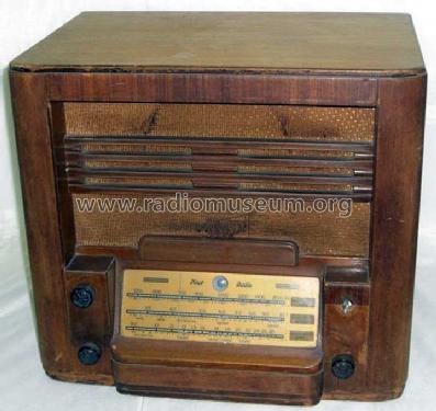
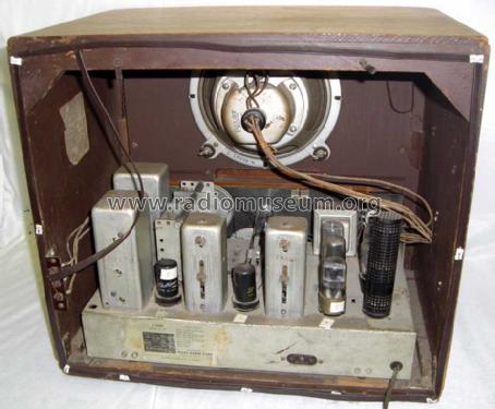
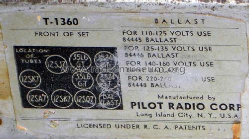
- Modell: T-1360 - Pilot Electric Mfg. Co. Radio
- Form
- Tischgerät, Hochformat (höher als quadratisch, schlicht, keine Kathedrale).
- Abmessungen (BHT)
- 16 x 18 x 12 inch / 406 x 457 x 305 mm
- Bemerkung
- For the Pilot model T-1360, different ballast tubes are used for 117 V, 130 V, 150 V or 230 V mains supply: For 110-125 volts 84445, for 125-135 volts 84446, for 140-160 volts 84447 or for 220-240 volts 84448. Built-in loop antenna; push-pull AF output stage; magic eye. The set has a manufacturer plate Pilot Radio Corp., Long Island City, N.Y., USA. The ballast tube is listed but not counted for. Height/Width may be reverse.
- Datenherkunft extern
- Guest James Lautwein, Joliet, IL, USA
- Autor
- Modellseite von Ernst Erb angelegt. Siehe bei "Änderungsvorschlag" für weitere Mitarbeit.
- Weitere Modelle
-
Hier finden Sie 544 Modelle, davon 273 mit Bildern und 412 mit Schaltbildern.
Alle gelisteten Radios usw. von Pilot Electric Mfg. Co. (Radio Corp.); Brooklyn (NY)
Forumsbeiträge zum Modell: Pilot Electric Mfg.: T-1360
Threads: 1 | Posts: 3
These photo's are of MY radio as purchased off e-bay.
I have no problem with that, just curious how they got posted here.
The Eye tube turns out was a 6AB5. I replaced it with a 6N5
The closest schematic for this is the Model T-1364
I have finished restoration and was looking for more info on it.
Bob T
Wilmington, NC
Bob Timms, 08.Jun.11