- Land
- USA
- Hersteller / Marke
- RCA (RCA Victor Co. Inc.); New York (NY)
- Jahr
- 1937
- Kategorie
- Rundfunkempfänger (Radio - oder Tuner nach WW2)
- Radiomuseum.org ID
- 53766
-
- anderer Name: RCA Manufacturing || Victor Talking Machine
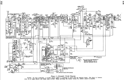
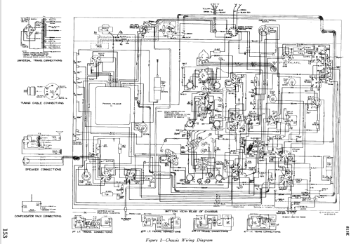

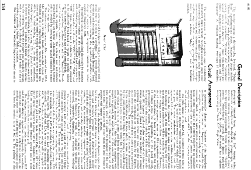

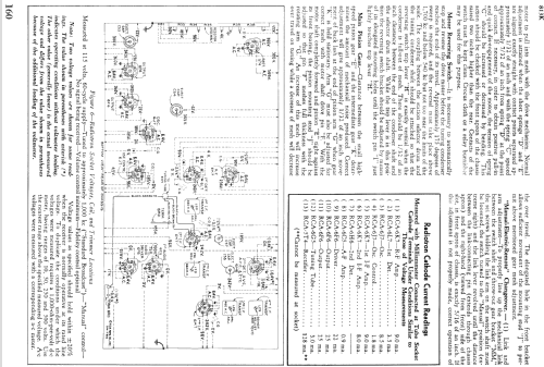
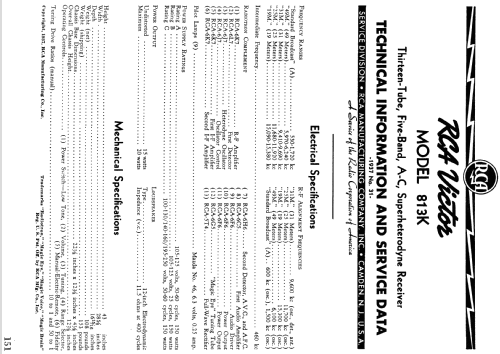


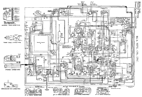


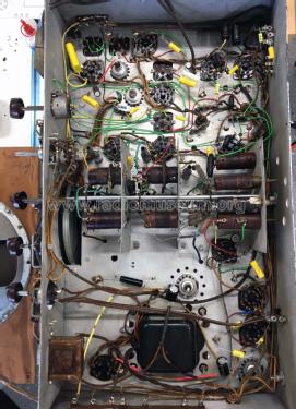


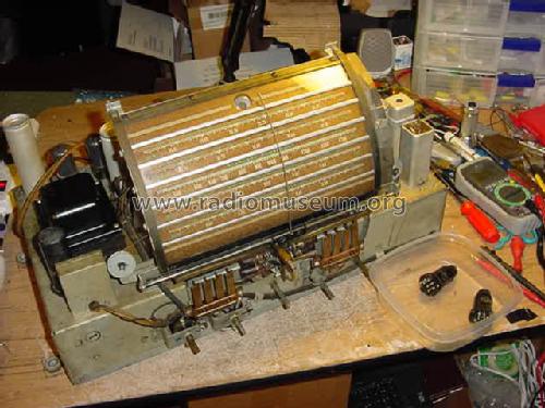
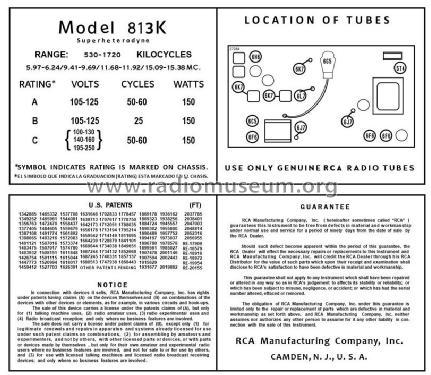
RCA 813K chassis
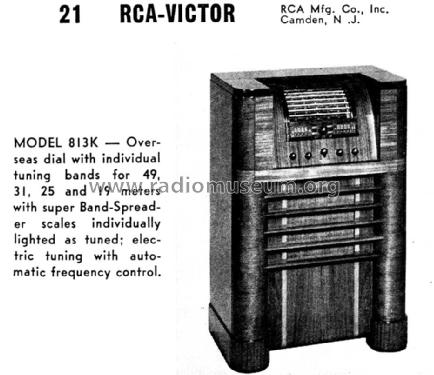
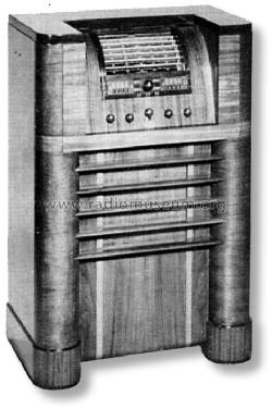
Scanned from the Radio Retailing June 1937.
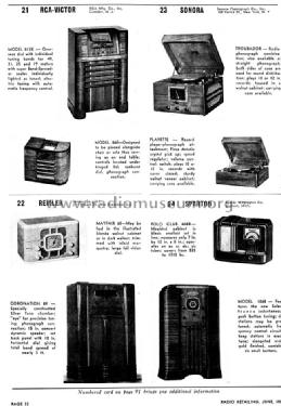
Scanned from the Radio Retailing June 1937.
Ebay Seller willeezwarez Item 261011720249

RECONSTRUCTED LABEL

RECONSTRUCTED LABEL
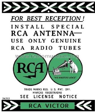
RECONSTRUCTED LABEL
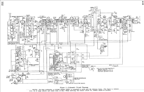
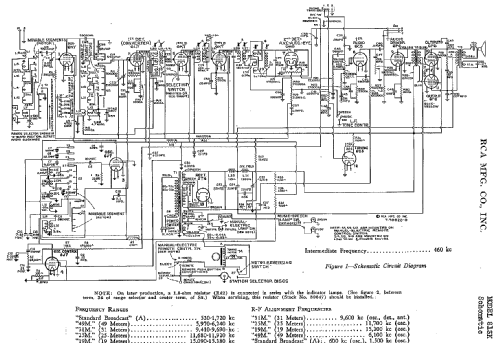
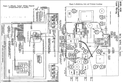
Klicken Sie auf den Schaltplanausschnitt, um diesen kostenlos als Dokument anzufordern.
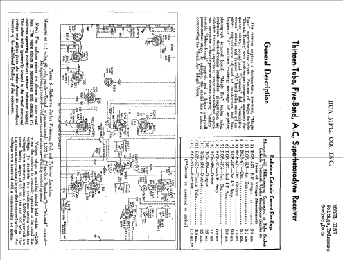
- Anzahl Röhren
- 13
- Hauptprinzip
- Super mit HF-Vorstufe; ZF/IF 460 kHz
- Wellenbereiche
- Mittelwelle und mehr als 2 x Kurzwelle.
- Betriebsart / Volt
- Wechselstromspeisung / 105-125 Volt
- Lautsprecher
- Dynamischer LS, mit Erregerspule (elektrodynamisch) / Ø 12 inch = 30.5 cm
- Belastbarkeit / Leistung
- 15 W (Qualität unbekannt)
- Material
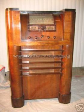
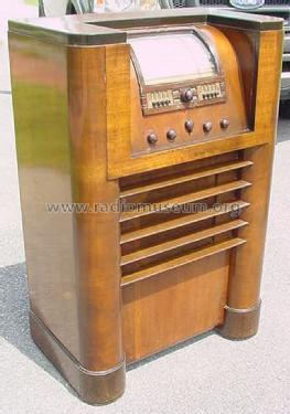
- Gerät mit Holzgehäuse
- von Radiomuseum.org
- Modell: 813K - RCA RCA Victor Co. Inc.; New
- Form
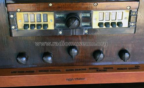
- Standgerät mit Drucktasten.
- Abmessungen (BHT)
- 28.625 x 43 x 17 inch / 727 x 1092 x 432 mm
- Bemerkung
- BC and 4xSW.
There is also the similar canadian model 813K.
- Datenherkunft extern
- Ernst Erb
- Schaltungsnachweis
- Rider's Perpetual, Volume 9 = 1938 and before
- Literaturnachweis
- Collector's Guide to Antique Radios 4. Edition
- Literatur/Schema (1)
- Pre-War Consoles
- Literatur/Schema (2)
- RCA Victor Service Notes for 1937 (RCA Redbook)
- Literatur/Schema (3)
- Radio Retailing (Radio & Television R.) (June 1937.)
- Weitere Modelle
-
Hier finden Sie 5180 Modelle, davon 3254 mit Bildern und 4217 mit Schaltbildern.
Alle gelisteten Radios usw. von RCA (RCA Victor Co. Inc.); New York (NY)
Sammlungen
Das Modell 813K befindet sich in den Sammlungen folgender Mitglieder.
Forumsbeiträge zum Modell: RCA RCA Victor Co.: 813K
Threads: 1 | Posts: 9
I'm restoring an 813K and had a few questions, the cabinet is finished and now working on the electronics. The bezel was my greatest challenge it had shrunk and twisted over time I guess or maybe was left in the sun. I completely re-fabricated one out of wood except for the lower part. Lettering for the knobs was not visible for the two left knobs. Far left is power 2nd from left not sure.So looking for the exact wording for the knobs? Wood working is my forte electronics not so much.
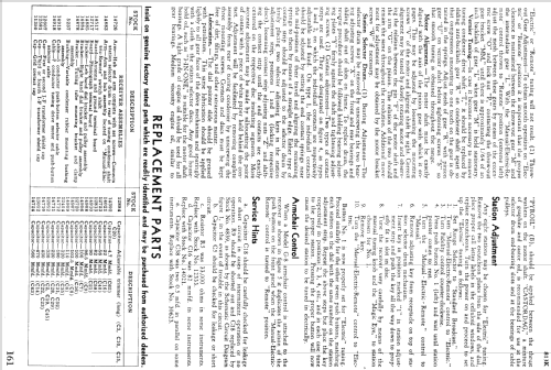
I have replaced all the capacitors and found one electrolyte C56 (20mfd) with positive going to ground. That doesn't seem right to me but it appears to be from the factory. Does that seem right to you?
The schematics that I have do not indicate polarity on any of the electrolytes. C53 (25mfd), C54 (25mfd), C55 & C57 (both 16mfd) were in cans. C53 & C54 had tabs between non-conductive wafers and wires were connected to the tabs. Unfortunately I didn't pay attention to how these wafers were placed, but assume they were to isolate the can from the tab. So my question is this: with only one lead coming out of the top of these cans (which i assume to be +) where does the negative lead go? My assumption is to the tabs? But from inside the can how does the negative lead get to the tabs?
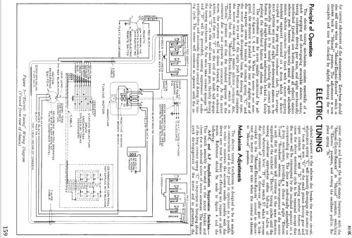
On the top of the drive motor for electronic tuning there is (what appears to be a capacitor) with absolutely no markings on it and I can't find it on the schematic anywhere. but again my electronic knowledge leaves a lot to be desired.
I know this a lot but would appreciate any help anyone can offer.
Jim Hochstetler
361-442-7435
Headline edited and post moved to model
James Hochstetler, 11.Nov.21