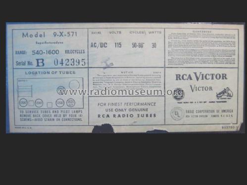
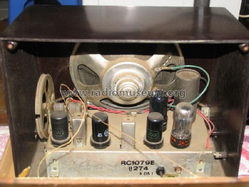
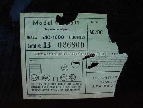
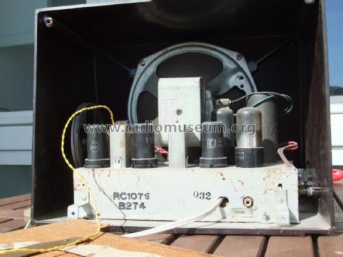
9-X-571 Ch= RC-1079
RCA (RCA Victor Co. Inc.); New York (NY)
- Land
- USA
- Hersteller / Marke
- RCA (RCA Victor Co. Inc.); New York (NY)
- Jahr
- 1949
- Kategorie
- Rundfunkempfänger (Radio - oder Tuner nach WW2)
- Radiomuseum.org ID
- 54105
-
- anderer Name: RCA Manufacturing || Victor Talking Machine
Beitman
Rider
Rider

Complete Restoration

Complete Restoration
Complete Restoration
Complete Restoration
Complete Restoration
By Courtesy Of EBAY User: akachuck
Copy gen. von Art Hoch Radio Attic

By courtesy of William Kendrick, USA
By courtesy of William Kendrick, USA
Q = Ebay objnr : 150121826921


By Courtesy Of EBAY User: akachuck
By Courtesy Of EBAY User: akachuck
By Courtesy Of EBAY User: akachuck
By Courtesy Of EBAY User: akachuck
By Courtesy Of EBAY User: akachuck
By Courtesy Of EBAY User: akachuck

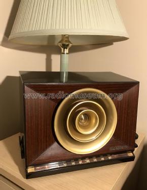
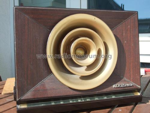
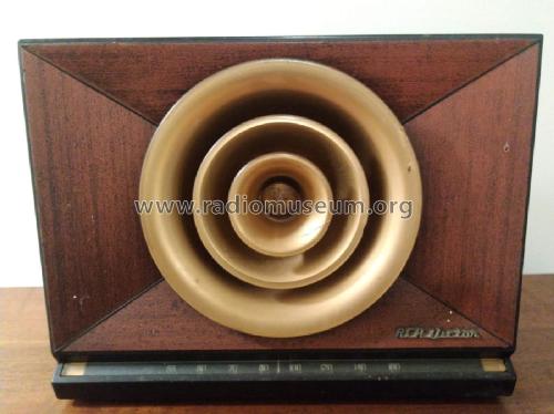
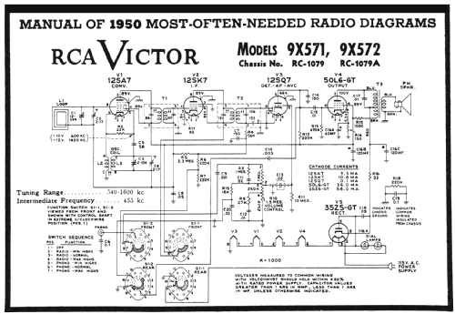
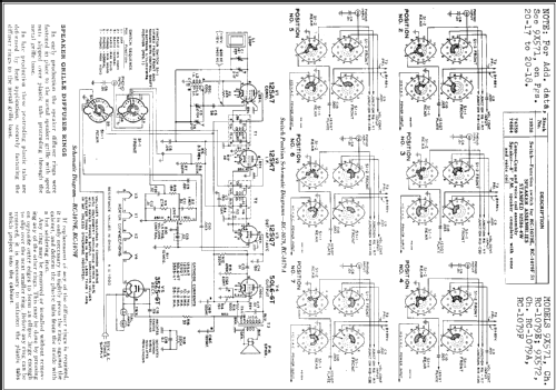
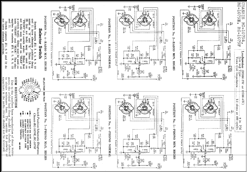
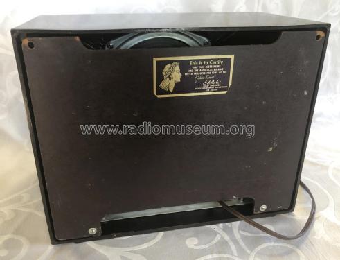
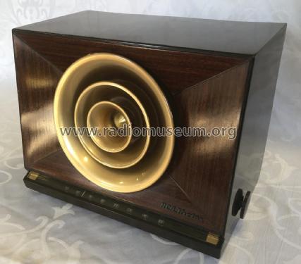
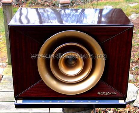
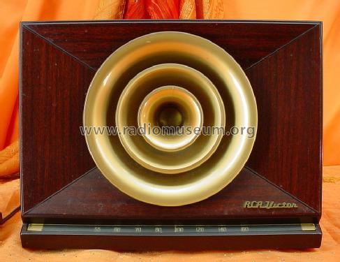
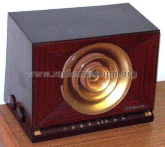
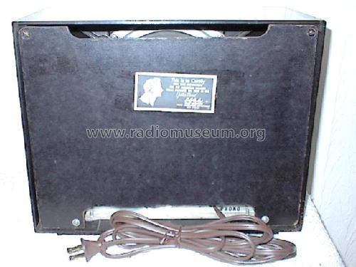
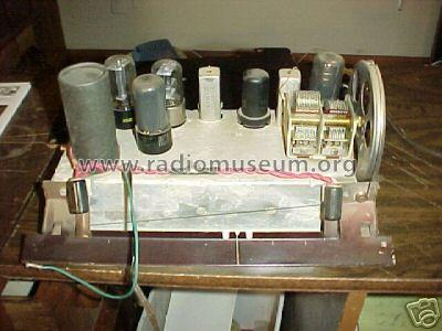
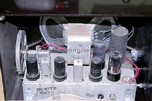
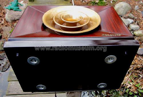
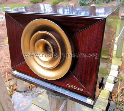
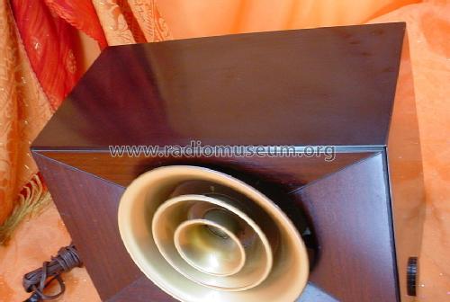
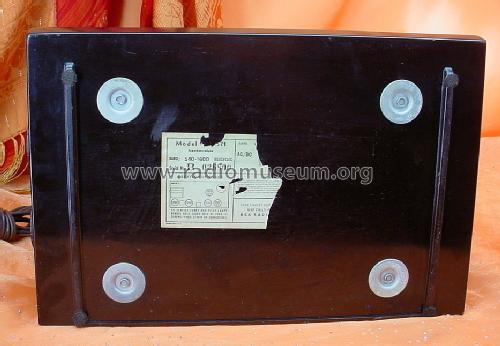
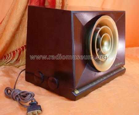
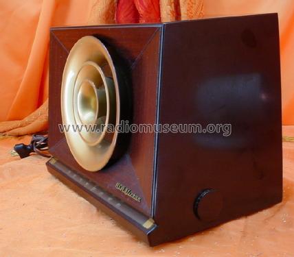
RCA Victor 9-X-571.
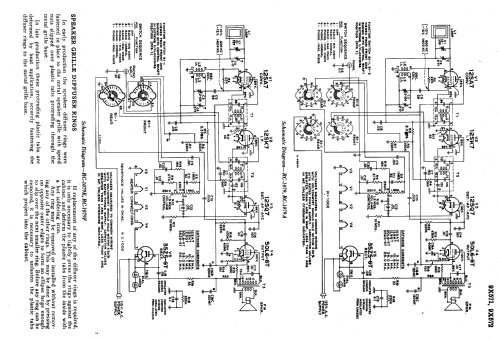
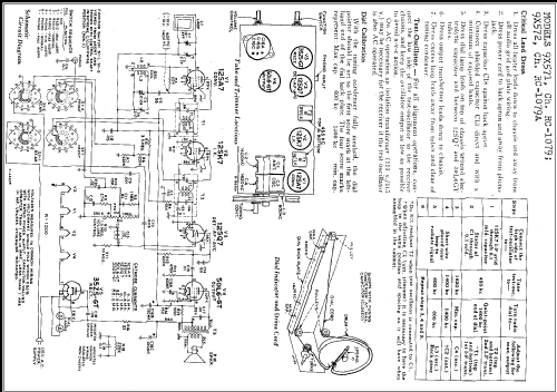
Klicken Sie auf den Schaltplanausschnitt, um diesen kostenlos als Dokument anzufordern.
- Anzahl Röhren
- 5
- Hauptprinzip
- Superhet allgemein; ZF/IF 455 kHz; 2 NF-Stufe(n)
- Anzahl Kreise
- 6 Kreis(e) AM
- Wellenbereiche
- Mittelwelle, keine anderen.
- Betriebsart / Volt
- Allstromgerät / 115 Volt
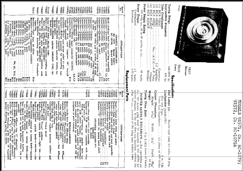
- Lautsprecher
- Dynamischer LS, keine Erregerspule (permanentdynamisch) / Ø 8 inch = 20.3 cm
- Belastbarkeit / Leistung
- 1.75 W (Qualität unbekannt)
- Material
- Bakelit (Pressstoff)
- von Radiomuseum.org
- Modell: 9-X-571 Ch= RC-1079 - RCA RCA Victor Co. Inc.; New
- Form
- Tischgerät ohne Drucktasten, bis 35 cm Breite (Kleingerät, meist dekorativ. Nur für Netzbetrieb, doch Transportgriff möglich).
- Abmessungen (BHT)
- 320 x 240 x 210 mm / 12.6 x 9.4 x 8.3 inch
- Bemerkung
- RCA Victor Model 9X-571 shows the color: maroon. Similar model 5-X-572 (#5X572) is in ivory. Dial lamps: 2 Mazda type 1490, 3.2V, 0.16 amp.
- Nettogewicht
- 4.6 kg / 10 lb 2.1 oz (10.132 lb)
- Datenherkunft extern
- Ernst Erb
- Schaltungsnachweis
- Rider's Perpetual, Volume 20 covering 1950
- Literaturnachweis
- Collector's Guide to Antique Radios 4. Edition
- Literatur/Schema (1)
- RCA Victor Instruments Service Notes 1949
- Weitere Modelle
-
Hier finden Sie 5179 Modelle, davon 3252 mit Bildern und 4216 mit Schaltbildern.
Alle gelisteten Radios usw. von RCA (RCA Victor Co. Inc.); New York (NY)
Sammlungen
Das Modell 9-X-571 befindet sich in den Sammlungen folgender Mitglieder.
Forumsbeiträge zum Modell: RCA RCA Victor Co.: 9-X-571 Ch= RC-1079
Threads: 1 | Posts: 4
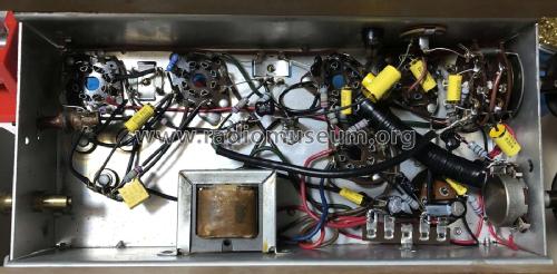
Static during reception with this model is often caused by internal leakage in the IF transformers caused by silver creap in the internal capacitors that causes leakage current between the primary and secondary.
Note: use care when desoldering and soldering to these IF transformer pins because excessive heat will cause the plastic base surrounding the pin to melt and the pin to loosen which can cause internal connections to break.
This leakage can be checked by disconnecting the secondary (both terminals) of the IF transformer. Test one transformer at a time. Temporarily connect the two wires together that were disconnected from the transformer secondary so the remaining radio circuitry will not be an open circuit. Connect a high impedance DC voltmeter, such as a vacuum tube voltmeter or a digital voltmeter, to either of the disconnected secondary terminals. Turn on the radio and check for the presence of any DC voltage reading on the meter. This might be a jumpy reading. A transformer with good capacitors will not have any voltage during this test.
If leakage is found it can usually be eliminated by disassembling the IF transformer and making repairs. Sometimes careful visual inspection will show black wiskers on the mica capacitor sheet between the primary and secondary sides which can be scraped away. Sometimes the mica sheets can be carefully cut or broken to separate the primary side from the secondary side. Sometimes the mica sheet capacitors must be disconnected or removed and replaced by temperature-stable ceramic or mica capacitors.
Paul Moyer, 24.Jan.07