K130 Ch= RC-501A
RCA (RCA Victor Co. Inc.); New York (NY)
- País
- Estados Unidos
- Fabricante / Marca
- RCA (RCA Victor Co. Inc.); New York (NY)
- Año
- 1939
- Categoría
- Radio - o Sintonizador pasado WW2
- Radiomuseum.org ID
- 54301
-
- alternative name: RCA Manufacturing || Victor Talking Machine


Ebay Nr. 280038020189 Bild bearbeitet.
Ebay Nr. 280038020189 Bild bearbeitet.
Ebay Nr. 280038020189 Bild bearbeitet.
Ebay Nr. 280038020189 Bild bearbeitet.
Ebay Nr. 280038020189 Bild bearbeitet.
Ebay Nr. 280038020189 Bild bearbeitet.
Ebay Nr. 280038020189 Bild bearbeitet.


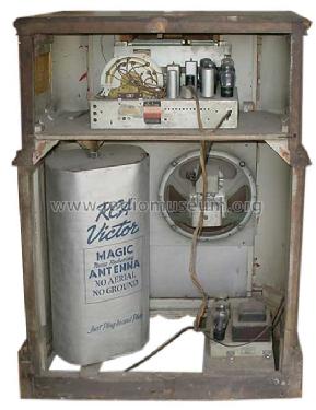
Back
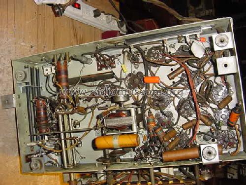
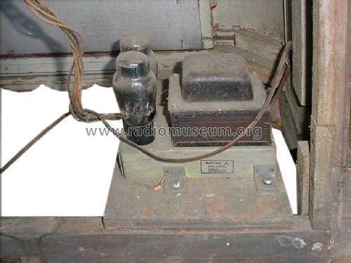
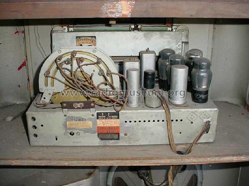
under chassis
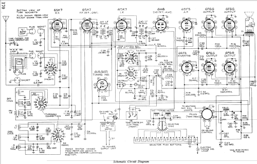
Haga clic en la miniatura esquemática para solicitarlo como documento gratuito.
- Numero de valvulas
- 13
- Principio principal
- Superheterodino con paso previo de RF; ZF/IF 455 kHz
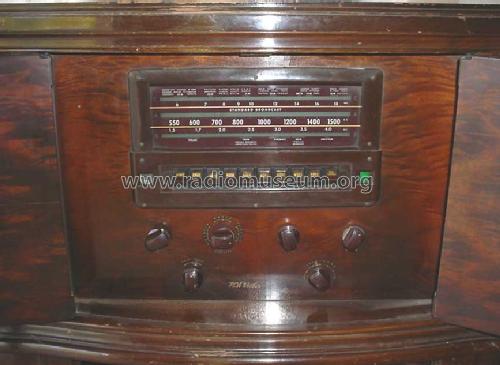
- Gama de ondas
- OM y dos OC
- Tensión de funcionamiento
- Red: Corriente alterna (CA, Inglés = AC)
- Altavoz
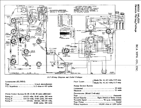
- Altavoz electrodinámico (bobina de campo) / Ø 12 inch = 30.5 cm
- Potencia de salida
- 20 W (unknown quality)
- Material
- Madera
- de Radiomuseum.org
- Modelo: K130 Ch= RC-501A - RCA RCA Victor Co. Inc.; New
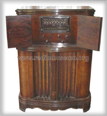
- Forma
- Consola con botonera.
- Ancho, altura, profundidad
- 32.375 x 44 x 17 inch / 822 x 1118 x 432 mm
- Anotaciones
- Doors. Motorized tuning.
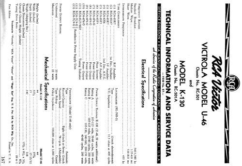
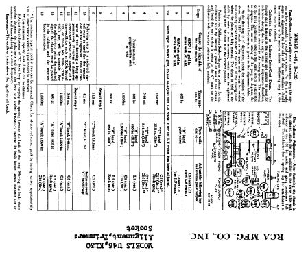
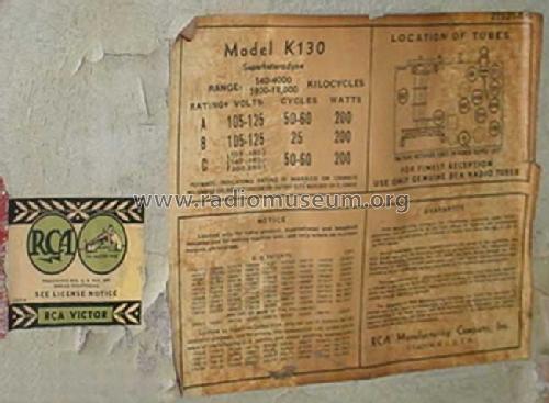
This model has 3 power supply ratings:
Rating A...105-125V, 50-60 Cycles
Rating B...105-125V, 25-60 Cycles
Rating C...105-130;140-160;200-250V, 40-60 Cycles
- Peso neto
- 63.56 lb (63 lb 9 oz) / 28.856 kg
- Precio durante el primer año
- 159.95 USD
- Ext. procedencia de los datos
- Ernst Erb
- Procedencia de los datos
- The Radio Collector's Directory and Price Guide 1921 - 1965
- Referencia esquema
- Rider's Perpetual, Volume 11 = ca. 1940 and before
- Mencionado en
- Collector's Guide to Antique Radios 4. Edition
- Documentación / Esquemas (1)
- Pre-War Consoles
- Documentación / Esquemas (2)
- RCA Victor Service Notes "Red Book" Series
- Otros modelos
-
Donde encontrará 5144 modelos, 3250 con imágenes y 4182 con esquemas.
Ir al listado general de RCA (RCA Victor Co. Inc.); New York (NY)
Colecciones
El modelo K130 es parte de las colecciones de los siguientes miembros.
Contribuciones en el Foro acerca de este modelo: RCA RCA Victor Co.: K130 Ch= RC-501A
Hilos: 1 | Mensajes: 1
Some tips for repairing the motorized tuning system on the RCA K130 and other similar models:
First I had to replace the AC motor drive capacitor, which is a 60 uF 24 VAC nonpolarized electrolytic capacitor. I used back-to-back (the two + ends connected) polarized electrolytic capacitors, first trying two 50 uF 50 VDC capacitors, and then two 100 uF 50 VDC capacitors. The two 100 uF capacitors provided better motor torque, so I went with those.
Although it worked OK without them, I also added 1N4007 diodes across each capacitor to prevent any reverse polarity voltage from damaging the caps. This might extend the life of the replacement capacitors.
If the motor runs a long time (more than a minute -- much longer than needed for the tuning to operate), the caps start to get a little warm, but they seem to be holding up just fine. The original cap is marked "intermittent usage," so I imagine these replacement caps have similar capability.
Also found that the rubber drive "wheel" on the motor shaft was hard as a rock and would not grip its mating metal wheel. Simply using the spinning motor shaft itself as a lathe with a little knife blade, I turned down the rubber to remove about half of it, and exposing the end of the metal shaft. Then I glued a plain rubber grommet to the remaining hard rubber and metal shaft with cyanoacrylate glue ("Super Glue," which sticks super well to rubber!). It works really well, with quiet, smooth operation, and plenty of torque transfer. Very simple fix for an otherwise difficult to obtain part.
The insulation on the two wires connected to the rotating split plate on the rear of the tuning capacitor was in bad shape, so I replaced those wires with modern very finely stranded (highly flexible) wire. This should hold up well for many years.
After these fixes, the motorized tuning system works perfectly.
Tom
Thomas Albrecht, 12.Mar.12