FM Stereo/AM Digital Receiver DT-800C
Sangean; Chung Ho City
- Fabricant / Marque
- Sangean; Chung Ho City
- Année
- 2019 ?
- Catégorie
- Radio - ou tuner d'après la guerre 1939-45
- Radiomuseum.org ID
- 333122


Pictures from AliExpress SANGEAN store.

Pictures from AliExpress SANGEAN store.


Cliquez sur la vignette du schéma pour le demander en tant que document gratuit.
- Principe général
- DSP, traitement numérique du signal
- Gammes d'ondes
- PO et FM
- Tension / type courant
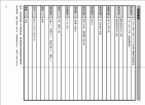
- Batteries / Alim. BT séparée avec fiche / AA: 2 x 1.5 or AA: 2 x 1.2 Volt
- Haut-parleur
- HP dynamique à aimant permanent + bobine mobile / Ø 2.8 cm = 1.1 inch
- Puissance de sortie
- 0.1 W (sans distorsion)
- Matière
- Plastique moderne (pas de bakélite, ni de catalin)
- De Radiomuseum.org
- Modèle: FM Stereo/AM Digital Receiver DT-800C - Sangean; Chung Ho City
- Forme
- Portable, appareil de poche. Taille < 20cm
- Dimensions (LHP)
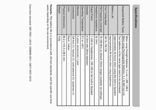
- 68.2 x 115.4 x 26.5 mm / 2.7 x 4.5 x 1 inch
- Remarques
-
The domestic Chinese model variant DT-800C shares a common design with the U.S. model (the AM/FM/WX DT-800) and with the European model (the Pocket 800 DT-800).
Despite the three model variants sharing a common set of features, each one has unique features suited to the target market.
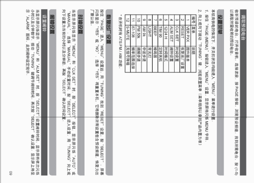
Main specifications for the domestic Chinese model:
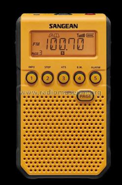
- Cabinet colors: Black and Yellow
- Receiver bands:
- FM-RDS: Selectable between
- 87-108 MHz
- 76-108 MHz
- 64-108 MHz
- 76-90 MHz
- Tuning steps: 100 kHz, 50 kHz, 10 kHz fine tuning, selectable
- Radio station name with RDS service
- AM: Selectable between
- 522-1710 kHz (9k tuning steps, 1 kHz fine tuning)
- 520-1710 kHz (10k tuning steps, 1 kHz fine tuning)
- FM-RDS: Selectable between
- 45 Memory Preset Stations (30 FM, 15 AM)
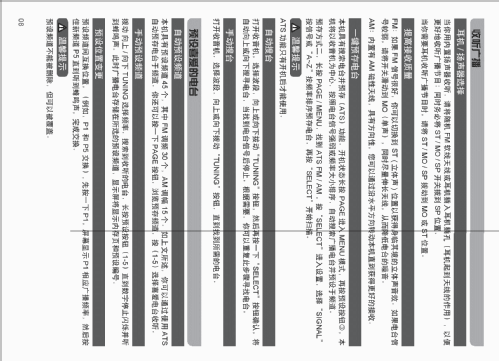
- Manual and Auto scan with ATS/APS
- Wide/Narrow Bandwith on AM and FM
- DSP Soft-Mute ON or OFF, selectable
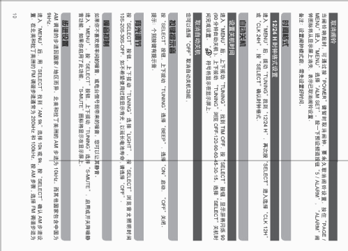
- Clock with Alarm (Buzzer) and Sleep timer
- Auto clock sync with RDS CT service
- Dynamic Bass Boost
- Battery level indicator
- Lock switch
- Stereo Earphone socket (FM)
- Built-in Speaker
- Built-in Ni-MH battery charger (USB charger port)
- Can run on penlight AA batteries, or on Ni-MH rechargealble batteries, selectable at the back of the unit inside the battery compartment.
The DT-800C variant has the following major differences compared to the DT-800 variants (US and European models):
- DT-800C secondary function of button 3 calls the ATS, while the DT-800 variants calls the S-MUTE.
- DT-800C have 45 memory presets (30 FM, 15 AM), while the DT-800 have 45 on the US variant (20 FM, 20 AM, 5 WX) and 40 on the European variant (20 FM, 20 AM)
- DT-800C have two bands (FM, AM), the same as for the DT-800 European variant, while the DT-800 US variant have three bands (FM, AM, WX)
- DT-800C ATS default sorting order uses Higher to Lower Signal Strength, while the DT-800 variants uses Lower to Higher Signal Frequency
Please see other DT-800 variants here:
- Taiwan: FM Stereo / AM Digital Receiver DT-800
- European: Pocket 800 DT-800
- U.S.: FM/AM/WX Digital Receiver DT-800
- Poids net
- 0.132 kg / 0 lb 4.7 oz (0.291 lb)
- Auteur
- Modèle crée par Jose Mesquita. Voir les propositions de modification pour les contributeurs supplémentaires.
- D'autres Modèles
-
Vous pourrez trouver sous ce lien 77 modèles d'appareils, 76 avec des images et 31 avec des schémas.
Tous les appareils de Sangean; Chung Ho City
Collections
Le modèle FM Stereo/AM Digital Receiver fait partie des collections des membres suivants.
Contributions du forum pour ce modèle: Sangean; Chung Ho: FM Stereo/AM Digital Receiver DT-800C
Discussions: 1 | Publications: 1
The DT-800C is the chinese domestic version of the DT-800 international variants. It shares the same chassis as used on the European and Taiwanese variants with some minor detail differences.
These radio models are built around the Si4731 DSP FM/AM receiver with RDS from Silicon Labs (IC1), with the exception of the American model that features Weather band and most probably uses a Si4737 DSP FM/AM/Weather band receiver with RDS (whether the American model uses the Si4737 device is not confirmed at this point, as someone would need to dismantle one of these units to find out).
The MW band uses a 5 cm ferrite bar antenna, while the FM band uses no less than 3 antennas, two of them internally and one from the earphones ground lead. The FM internal antennas uses PCB copper traces, one in a dedicated PCB assembly at the back cover, and the other is the ground plane of the Keyboard PCB assembly atr the front cabinet.
Sangean did not save costs on the audio amplifier stage, as it designed two dual-channel audio power amplifiers, one to drive the built-in speaker in BTL mode (IC21), and another to drive the stereo earphones socket (IC2). The later features DBB for increased bass response. Older production batches uses two 2073 Power ICs while later ones use TDA2822G devices.
An audio "Noise Down" feature (Soft-Mute that can be enabled or disable during operation) is implemented thru a XD RN1504 NPN dual transistor with built-in bias resistors switching device (Q1), where the inputs shorted together are connected to the "Noise Down" signal from MCU assembly at the CN3/CN303 socket. The outputs enables LP filters in parallel with the IC301 DSP audio output lines.
The DBB Bass boost feature uses another XD RN1504 (Q2) where the inputs shorted together are connected to DBB switch SW1. The outputs enable DBB filters to IC2 headphone amplifier.
The USB Power Supply uses a H360X VRH3601NT 3.6V (IC101) for USB operation/charging. The input is connected to +5V from the USB port thru a S24 SSA24 (D101) schottky rectifier.
The USB charging is controlled by the MCU. When the Dry-cells/rechargeable-cells selector inside the battery compartment (SW3) is ON (set to NI-MH), it grounds the "B CHK" signal on CN103 going to the corresponding IC301 MCU input. Under program control logic, the MCU then uses the "CH" signal to enable charging, by driving the Q114 L6 2SC1623 base. Only discrete components are used in the charger, namely the Q113 AE 2SA1365 and the Q111 3403 MTP3403N3. P-MOSFET.
Each NI-MH battery is individually monitored by the MCU (IC301). A 7W66 TC7W66FK Dual Bilateral Switch (IC102) is used to monitor each cell. I/O1 switch enable monitoring battery A (1). I/O2 switch enable monitoring battery B (2). The MCU enables each I/O switch in order to read either one of the two battery voltage points:
- I/O switch 1
- I/O1-CT-7 to A8C MMUN2213 (Q104) collector, and base to "BATT A1" on CN103 from the MCU.
- I/O1-2 to +1V5 on CN2 (Battery socket white wire, 1.5V on dry, 1.2V on Ni-MH)
- I/O1-1 to "BATT D3ET" on CN103 to the MCU.
- I/O switch 2
- I/O2-CT-3 to A8C MMUN2213 (Q103) collector, and base to "BATT B1" on CN103 from the MCU.
- I/O2-6 to +3V on CN2 (Battery socket red wire, 3V on dry, 2.4V on Ni-MH)
- I/O2-5 to "BATT D3ET" on CN103 to the MCU.
The MCU uses a R5F10WMCA (IC301). A 4-pin pads with 3V3, FLMD0, GND, and RST signals was left without an header socket. A 402A XC6105A133MR 3.3V (IC302) is used as Voltage Detector for MCU reset. A miniature supercap (C303) is used as a battery backup. A few discrete transistors are used, like a L6 2SC1623 NPN (Q301), M6 2SA812 PNP (Q302), and L6 2SC1623 NPN (Q303). The LCD is soldered directly to the MCU assembly using 36-pin flat cable wires.
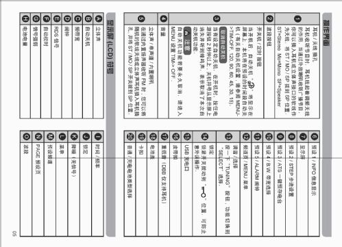
The front panel Keyboard assembly uses only a 4-pin interconnector (TIP301). The GND signal is used as FM antenna. The RETURN signal is common for all the 6 keys. KEY2 signal is dedicated to the MENU key (SW506). KEY1 signal uses a 5 point voltage divider with 5 series resistors, one per key:
- M1 SW501
- M2 SW502
- M3 SW503
- M4 SW504
- M5 SW505
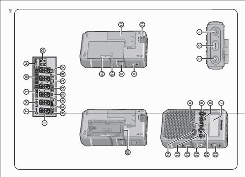
Internally, these radio models have five PCB assemblies:
- Receiver assembly - P/N 16A1124A MP-V1.40 PCB-A
- Internal back side FM Antenna 1 assembly - P/N 16A1240A MP-V1.00 PCB-B
- MCU/Display Assembly - P/N 16A1124A-1 MP-V1.40
- KB / FM Antenna 2 assembly - P/N 16A1124A-2 MP-V1.40
- Tuning/Select PCB assembly - Tiny PCB with the Encoder for T-D, T-U, Return, and Center
Additionally, glued to the front cover are the MW ferrite bar antenna with around 5cm long, as well as the built-in speaker with 8Ω, 0.5W, P/N 1622310.
For additional details, please see the block diagram uploaded to the Sangean DT-800 European model version.
Jose Mesquita, 06.Nov.22