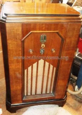
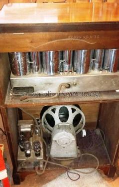
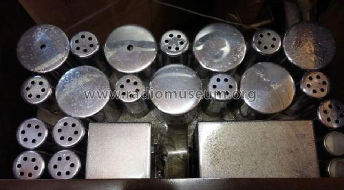
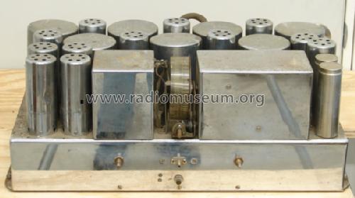
All Wave (Allwave) 15 (Chrome CHASSIS)
Scott Radio Labs.(E.H., Transformer); Chicago (IL)
- Country
- United States of America (USA)
- Manufacturer / Brand
- Scott Radio Labs.(E.H., Transformer); Chicago (IL)
- Year
- 1934
- Category
- Broadcast Receiver - or past WW2 Tuner
- Radiomuseum.org ID
- 55360


From the collection of Howard Stone.

Click on the schematic thumbnail to request the schematic as a free document.
- Main principle
- Superheterodyne (common)
- Wave bands
- Broadcast and Short Wave (SW).
- Power type and voltage
- Alternating Current supply (AC) / 110 Volt
- Material
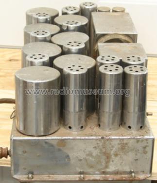
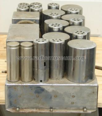
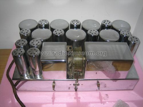
- Metal case, TUBES VISIBLE
- from Radiomuseum.org
- Model: All Wave 15 - Scott Radio Labs.E.H.,
- Shape
- Chassis only or for «building in»
- Notes
-
The Scott Allwave 15 was introduced in 1934 and was designed to replace the earlier Scott Allwave 12. New features were the addition of a tuning meter driver tube, BFO, and push pull audio driver stage. The audio output was increased by replacing the push pull 45 valves with 2A3’s. There were two versions of the Allwave 15, an early version which had a 55, 2nd detector tube set up as a half wave detector and a late version which had the 55, 2nd detector tube set up as a full wave detector.
Frequency Ranges:
BC Band (White Band)...540 kHz - 1500 kHz
SW-1 Band (Green Band)...1.5 MHz - 4 MHz
SW-2 Band (Red Band)...4 MHz - 10 MHz
SW-3 Band (Purple Band)...10 MHz - 23 MHz.
- External source of data
- Ernst Erb
- Source of data
- The Radio Collector's Directory and Price Guide 1921 - 1965
- Circuit diagram reference
- Rider's Perpetual, Volume 15 = 1947 and before
- Mentioned in
- E.H.Scott Radio Collectors Guide (1925-1946)
- Literature/Schematics (1)
- Australian HRSA Radio Waves, January 1997, Page 9
- Other Models
-
Here you find 201 models, 126 with images and 51 with schematics for wireless sets etc. In French: TSF for Télégraphie sans fil.
All listed radios etc. from Scott Radio Labs.(E.H., Transformer); Chicago (IL)
Collections
The model All Wave (Allwave) is part of the collections of the following members.
Museums
The model All Wave (Allwave) can be seen in the following museums.