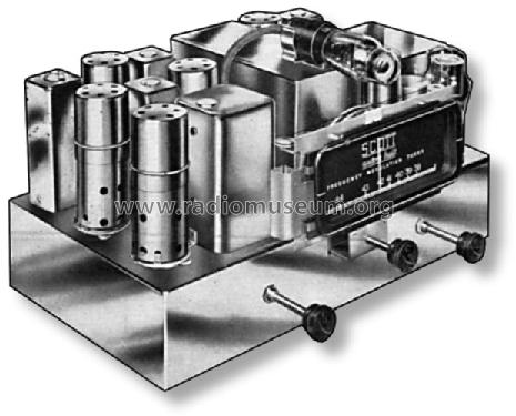
FM Tuner Chrome CHASSIS
Scott Radio Labs.(E.H., Transformer); Chicago (IL)
- País
- Estados Unidos
- Fabricante / Marca
- Scott Radio Labs.(E.H., Transformer); Chicago (IL)
- Año
- 1940
- Categoría
- Conversor o Adaptador de frecuencia
- Radiomuseum.org ID
- 55364
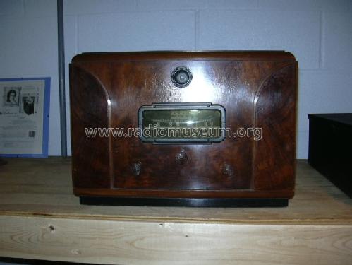
Scott FM Tuner in Mode Cabinet
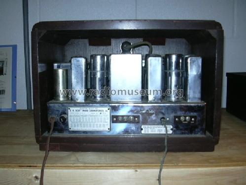
Scott FM Tuner - inside view
Haga clic en la miniatura esquemática para solicitarlo como documento gratuito.
- Numero de valvulas
- 10
- Principio principal
- Superheterodino en general
- Gama de ondas
- Solamente FM
- Tensión de funcionamiento
- Red: Corriente alterna (CA, Inglés = AC) / 110 Volt
- Altavoz
- - Este modelo usa amplificador externo de B.F.
- Material
- Metálico con lámparas a la vista.
- de Radiomuseum.org
- Modelo: FM Tuner Chrome CHASSIS - Scott Radio Labs.E.H.,
- Forma
- Chasis (tambien de autoradio)
- Anotaciones
- Old FM band 41-50 MHz.
Price with table cabinet 120 USD. Special cabinet Mod'e.
- Precio durante el primer año
- 110.00 $
- Ext. procedencia de los datos
- Ernst Erb
- Procedencia de los datos
- Guide to Old Radios
- Referencia esquema
- Rider's Perpetual, Volume 14 = 1944 = before 1943
- Mencionado en
- E.H.Scott Radio Collectors Guide (1925-1946) (.)
- Documentación / Esquemas (1)
- Scotts new Silver Ghosts
- Documentación / Esquemas (2)
- Pre-War Consoles
- Otros modelos
-
Donde encontrará 201 modelos, 126 con imágenes y 51 con esquemas.
Ir al listado general de Scott Radio Labs.(E.H., Transformer); Chicago (IL)
Colecciones
El modelo FM Tuner es parte de las colecciones de los siguientes miembros.
Contribuciones en el Foro acerca de este modelo: Scott Radio Labs.E.H: FM Tuner Chrome CHASSIS
Hilos: 1 | Mensajes: 1
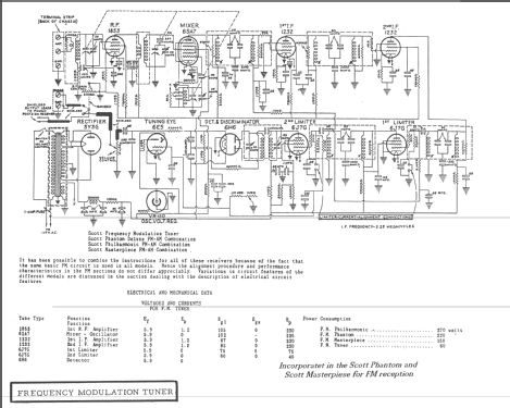
The Scott FM tuner starts with an 1853 high Gm tube as the RF amplifier. The output is transformer coupled to the mixer, a 6SA7 tube. The triode section of the 6SA7 is used as the local oscillator. A VR150 regulator stabilizes the oscillator plate supply, providing a stable IF output at 5.25 MHz. The IF amplification is passed through four stages. The first two stages are type 1232 high Gm tubes. The IF coupling is unique, using a combination of inductive tuning and capacitive coupling to minimize inductive coupling in the IF transformers. The third and fourth stages are generally referred to as the first and second limiters. This function is obtained from two 6J7 tubes, in a cascade limiter circuit. The grid-leak condenser combinations used in these stages determine the noise limiting time constants. The first limiter has a time constant of 2.5 microseconds. The second stage is at half that value. The discriminator/detector is a 6H6 dual diode. With a well balanced diode pair, the detector circuit should have a uniform response from 30 to 15000 cycles. The R/C circuit following the diode load is a correction for pre-emphasis of high audio frequencies imposed at the transmitter. Finally, a 6E5 tuning indicator is fed through a voltage divider/audio filter from the second limiter stage. The stand alone FM tuner unit has a 5Y3 rectifier for the power supply.
Kent King, 22.Aug.06