All-Wave 726SW (early version)
Silver - Marshall; Chicago, IL
- País
- Estados Unidos
- Fabricante / Marca
- Silver - Marshall; Chicago, IL
- Año
- 1931
- Categoría
- Radio - o Sintonizador pasado WW2
- Radiomuseum.org ID
- 57942
Short Wave Craft Dec31/Jan32 page 283

Short Wave Craft Dec31/Jan32 page 283
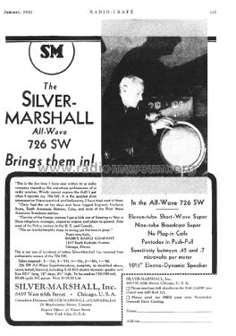
advert "Radio-Craft", Jan. 1932, own coll.
Haga clic en la miniatura esquemática para solicitarlo como documento gratuito.
- Numero de valvulas
- 11
- Principio principal
- Superheterodino doble o triple conversión; ZF/IF 175 kHz; Screengrid 1926-1935
- Número de circuitos sintonía
- 11 Circuíto(s) AM
- Gama de ondas
- OM y más de dos OC
- Tensión de funcionamiento
- Red: Corriente alterna (CA, Inglés = AC) / 110-120 Volt
- Altavoz
- Altavoz electrodinámico (bobina de campo) / Ø 10.5 inch = 26.7 cm
- Material
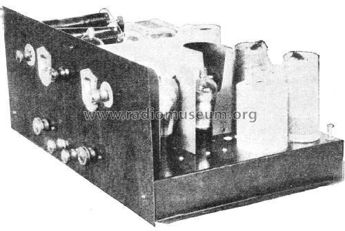
- Metálico con lámparas a la vista.
- de Radiomuseum.org
- Modelo: All-Wave 726SW - Silver - Marshall; Chicago, IL
- Forma
- Chasis (tambien de autoradio)
- Ancho, altura, profundidad
- 20.5 x 8.5 x 12 inch / 521 x 216 x 305 mm
- Anotaciones
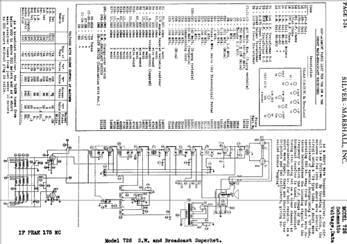
- If this model 726SW hat for the start the tube 35 or 235 then it can only be from May 1931 or later. One dial (primary tuning control knob); push-pull output stage. Probably only for the new version: As a short wave broadcast receiver, the antenna is fed into the short wave detector circuit using a 24 type tube. A short wave oscillator of special design using a '27 tube, operating at 650 kc away from the short wave detector heterodynes the incoming signal to the frequency to which the RF stage of the broadcast receiver is tuned, the broadcast tuning dial being set on a clear channel at approx. 650 kc for best results. As a short wave super, there are therefore three detectors and two oscillators, giving so called double "suping".
- Ext. procedencia de los datos
- Ernst Erb
- Procedencia de los datos
- Radio Collector`s Guide 1921-1932
- Referencia esquema
- Rider's Perpetual, Volume 1 = 1931/1934 (for 1919-1931)
- Otros modelos
-
Donde encontrará 225 modelos, 116 con imágenes y 122 con esquemas.
Ir al listado general de Silver - Marshall; Chicago, IL