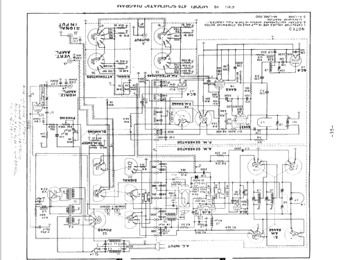
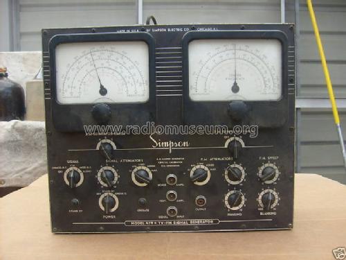
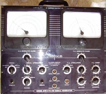
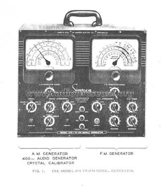
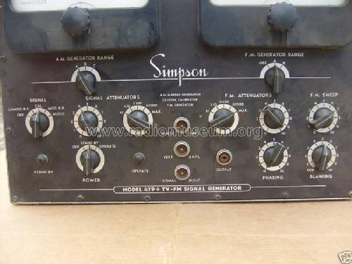
TV-FM Signal Generator 479
Simpson Electric Co.; Chicago, IL - Lac du Flambeau, WI
- Country
- United States of America (USA)
- Manufacturer / Brand
- Simpson Electric Co.; Chicago, IL - Lac du Flambeau, WI
- Year
- 1956
- Category
- Service- or Lab Equipment
- Radiomuseum.org ID
- 99232


Click on the schematic thumbnail to request the schematic as a free document.
- Number of Tubes
- 8
- Wave bands
- Wave Bands given in the notes.
- Power type and voltage
- Alternating Current supply (AC) / 105-125 Volt
- Loudspeaker
- - - No sound reproduction output.
- Material
- Metal case
- from Radiomuseum.org
- Model: TV-FM Signal Generator 479 - Simpson Electric Co.; Chicago,
- Shape
- Tablemodel, low profile (big size).
- Dimensions (WHD)
- 17 x 14 x 7.5 inch / 432 x 356 x 191 mm
- Notes
-
AM marker, FM sweep generator and crystal calibrator.
Marker generator:
- Fundamental and second harmonic
- Band A, 3.3 - 15.6 Mc
- Band B, 15 - 76 Mc
- Band C, 75 - 250 Mc
- Unmodulated or amplitude modulated 30% at 400 cycles
- 400 cycle audio signal
- Output attenuated with 2 controls: 1 step, 1 continuous
- Accuracy 0.1% using 5 Mc crystal
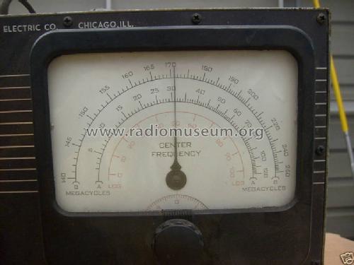
FM generator:
- Band A, 2 - 120 Mc
- Band B, 140 - 260 Mc
- Dial marked for harmonic use for UHF
- Sweep width continuously vriable, 0 though 15 Mc
- Sweep rate 60 cycles (line frequency)
Can be converted to color using Chromatic Probe and Chromatic Amplifier accessories.
Price including 2 oscilloscope cables, 1 impedance matching output cable, 1 signal input cable, manual and UHF instructions, in 1957: $325.00
- Net weight (2.2 lb = 1 kg)
- 29 lb 0 oz (29 lb) / 13.166 kg
- Price in first year of sale
- 319.00 $
- Mentioned in
- - - Manufacturers Literature (Simpson Test Equipment bulletin no. 2058, 1957)
- Literature/Schematics (1)
- Allied Radio Catalog (Knight) (Nº 150, 1956)
- Author
- Model page created by Vitor Oliveira. See "Data change" for further contributors.
- Other Models
-
Here you find 148 models, 131 with images and 60 with schematics for wireless sets etc. In French: TSF for Télégraphie sans fil.
All listed radios etc. from Simpson Electric Co.; Chicago, IL - Lac du Flambeau, WI
Collections
The model TV-FM Signal Generator is part of the collections of the following members.