TV-FM Signal Generator 479L
Simpson Electric Co.; Chicago, IL - Lac du Flambeau, WI
- Country
- United States of America (USA)
- Manufacturer / Brand
- Simpson Electric Co.; Chicago, IL - Lac du Flambeau, WI
- Year
- 1974 ??
- Category
- Service- or Lab Equipment
- Radiomuseum.org ID
- 193669
este é o meu gerador
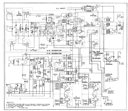
Click on the schematic thumbnail to request the schematic as a free document.
- Number of Tubes
- 6
- Main principle
- none
- Wave bands
- Wave Bands given in the notes.
- Power type and voltage
- Alternating Current supply (AC) / 110 Volt
- Loudspeaker
- - - No sound reproduction output.
- Material
- Metal case
- from Radiomuseum.org
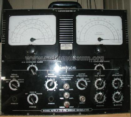
- Model: TV-FM Signal Generator 479L - Simpson Electric Co.; Chicago,
- Shape
- Tablemodel, low profile (big size).
- Dimensions (WHD)
- 355 x 430 x 190 mm / 14 x 16.9 x 7.5 inch
- Notes
- Two precision vernier dials, 20:1 knob to pointer ratio 1000 divisions logging scale. Horiz/vert signal amp output to oscilloscope. Three range RF generator with amplitude modulator 400 cycles audio oscillator with external input. x 1, x 10, x 100, x 1000 and max output attenuator rotative switch. RF modulator function Standby and operate position swich Phasing and blanking circuit AM generator Range: Band A: Fundamental > 3.3 to 7.8 MHz, second harmonic > 6.6 to 15.6 MHz Band B: Fundamental > 15 to 38 MHz, second harmonic > 30 to 76 MHz Band C: Fundamental > 75 to 125 MHz, second harmonic > 150 to 250 MHz FM generator Range: Band A: Fundamental > 5 to 120 MHz, second harmonic > 10 to 240 MHz Band B: Fundamental > 140 to 260 MHz, second harmonic > 280 to 520 MHz
- Net weight (2.2 lb = 1 kg)
- 15.2 kg / 33 lb 7.7 oz (33.48 lb)
- Author
- Model page created by Dirson Willig. See "Data change" for further contributors.
- Other Models
-
Here you find 148 models, 131 with images and 60 with schematics for wireless sets etc. In French: TSF for Télégraphie sans fil.
All listed radios etc. from Simpson Electric Co.; Chicago, IL - Lac du Flambeau, WI
Collections
The model TV-FM Signal Generator is part of the collections of the following members.