- País
- Estados Unidos
- Fabricante / Marca
- Singer Company, The; La Vergne, TN
- Año
- 1960 ??
- Categoría
- Televisión (TV) o monitor
- Radiomuseum.org ID
- 121928


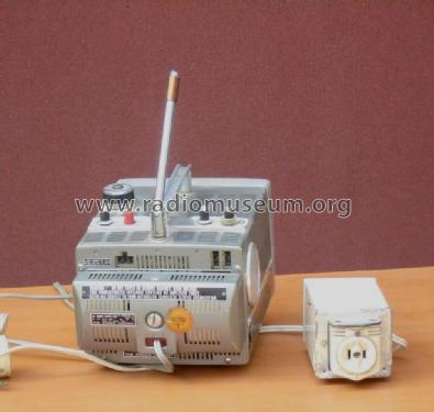
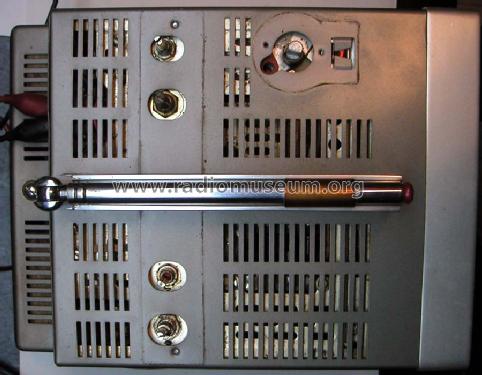
top under controls
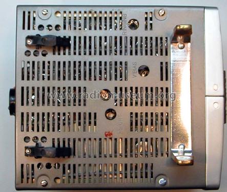
Aligator jumpers supply 13VDC
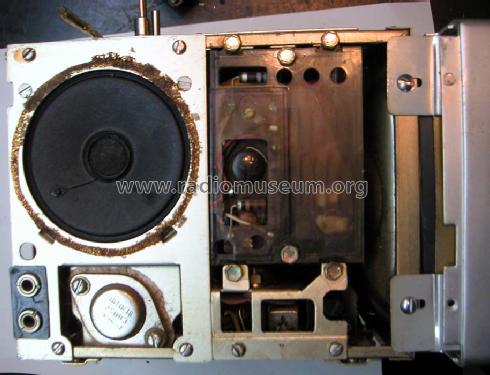
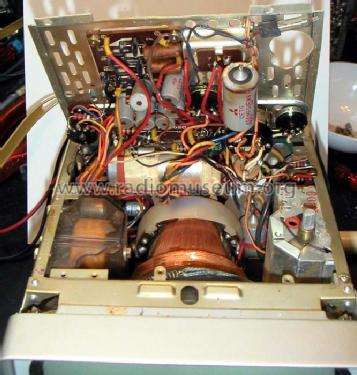
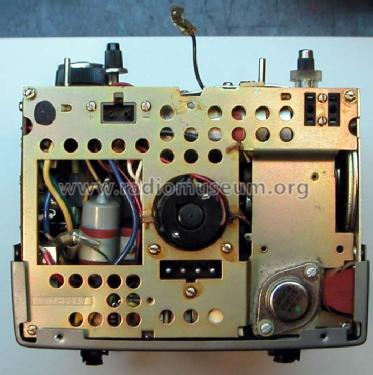
Speaker, 2SB88 supply regulator, HV block.
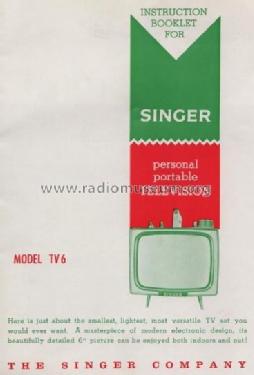
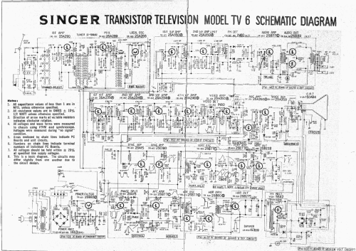
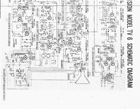
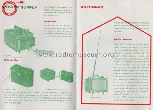
Instruction Booklet
Instruction Booklet
Haga clic en la miniatura esquemática para solicitarlo como documento gratuito.
- Numero de valvulas
- 2
- Numero de transistores
- 26
- Semiconductores
- Principio principal
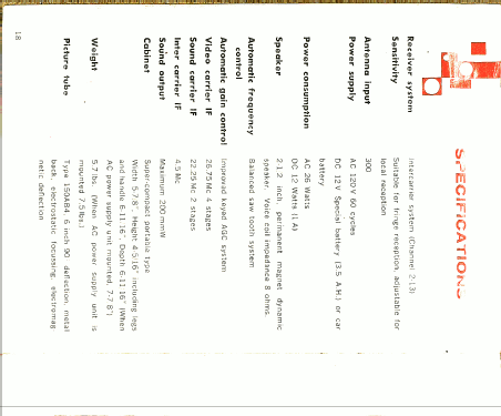
- Superheterodino en general
- Gama de ondas
- VHF/UHF (see notes for details)
- Tensión de funcionamiento
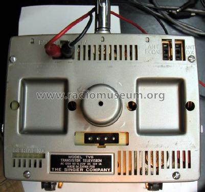
- Red / Acumuladores (posiblemente también baterias) / 115; 12 Volt
- Altavoz
- Altavoz dinámico (de imán permanente)
- Material
- Metálico
- de Radiomuseum.org
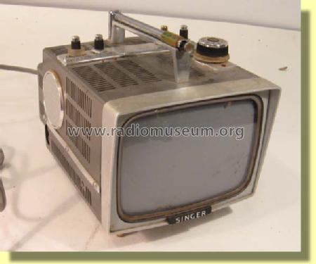
- Modelo: TV6 - Singer Company, The; La Vergne
- Forma
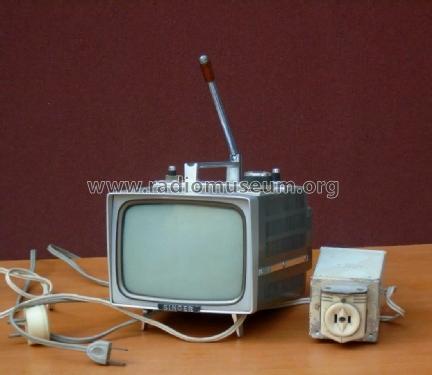
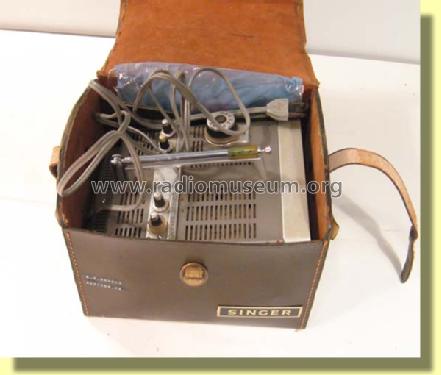
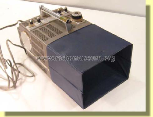
- Portátil > 20 cm (sin la necesidad de una red)
- Anotaciones
- 6" portable b/w TV, US band I/III drum tuner, built-in telescopic antenna, type TVA 3 was the special battery cord when used in a car.
- Procedencia de los datos
- -- Collector info (Sammler)
- Autor
- Modelo creado por un miembro de A. Ver en "Modificar Ficha" los participantes posteriores.
- Otros modelos
-
Donde encontrará 34 modelos, 27 con imágenes y 2 con esquemas.
Ir al listado general de Singer Company, The; La Vergne, TN
Colecciones
El modelo TV6 es parte de las colecciones de los siguientes miembros.
Contribuciones en el Foro acerca de este modelo: Singer Company, The;: TV6
Hilos: 1 | Mensajes: 1
Recent repair of two Singer TV6 units involved replacement of TR202 2SA234 in the second video IF stage. In one case the transistor was open, in the other case it developed excessive base resistance such that DC operation was OK, but there was no AC gain.
The IF frequency is not stated in the TV6 schematic, but I saw around 26MHz.
Before replacement of TR202, the set had no sound noise or image, but it had a white raster.
The electrical symptoms leading to the discovery of this common problem to both sets was a high gain of signal from 10mV p-p applied at the antena terminals for channel 10 around 200MHz, to the input of the second stage, while negligible signal appeared at the collector of TR202.
I got replacement transistors from a similar Singer TV6-U parts set. After these two transistors were replaced on each set there were still problems of a less severe nature. Note that the TV6-U is not just the TV6 with UHF added. The internal boards of the TV6-U look quite different from the internal boards of the TV6, which has no UHF.
One set had an open filter capacitor at the horizontal frequency control. It made horizontal lock impossible. This is C519 10uF at the Horizontal frequency control. probing the frequency control tap showed a large pulse train around 20Vp-p instead fo the expected pure DC control voltage.
This same set also had an open 100uF bypass capacitor C206 at the Video IF strip. This caused hum bars to roll vertically.
After these repairs, the remaining problem is poor vertical linearity on this set that with the two bad electrolytic caps. The linearity is bad enough that it can't be adjusted the with the vertical height, bias and linearity controls under the set. I have decided to put the set away for now, while documenting the work I did so far. The first thing I will check to solve the poor vertical linearity problem are the many electrolytic capacitors in the Vertical amplifier.
Comments invited.
-Joe Sousa
p.s.: A full scan of the manual showing all TV6 accessories and schematic is available at TV6_Manual
Joe Sousa, 09.Dec.08