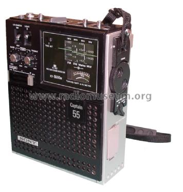
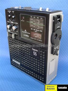
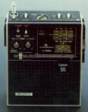
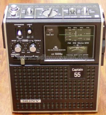
Captain 55 ICF-5500M
Sony Corporation; Tokyo
- Country
- Japan
- Manufacturer / Brand
- Sony Corporation; Tokyo
- Year
- 1973/1974
- Category
- Broadcast Receiver - or past WW2 Tuner
- Radiomuseum.org ID
- 86397


Original prospekt in cca.1974-1977.


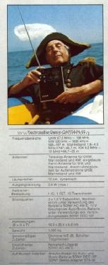
Original prospekt in cca.1974-1977.

Pic. just as type proof! - AM 468 kHz IF

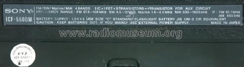
Typeplate, 2nd IF of 455 kHz mentionned
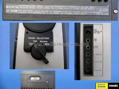
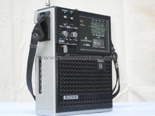
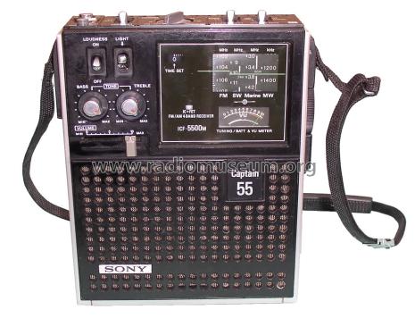
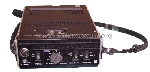
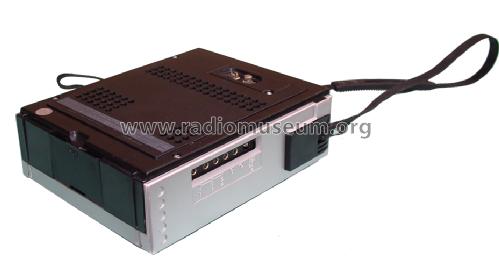

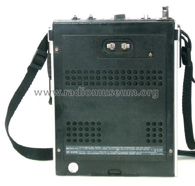
Photo de mon appareil

Photo de mon appareil

Photo de mon appareil
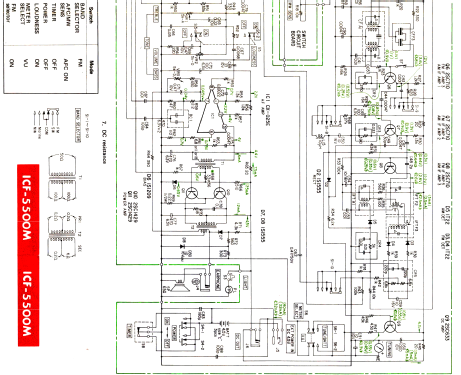
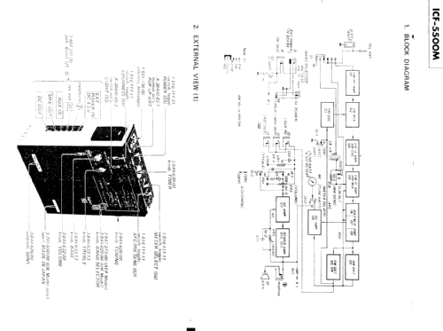
Click on the schematic thumbnail to request the schematic as a free document.
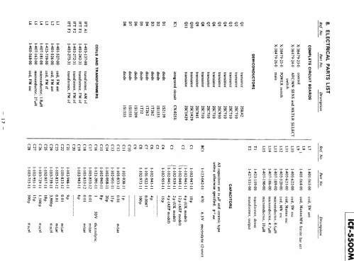
- Number of Transistors
- 10
- Semiconductors
- Main principle
- Superheterodyne (common); ZF/IF 455 or 468/10700 kHz
- Tuned circuits
- 6 AM circuit(s) 7 FM circuit(s)
- Wave bands
- Broadcast, 2 Short Wave plus FM or UHF.
- Power type and voltage
- Dry Batteries / (3 x 1,5) Volt
- Loudspeaker
- Permanent Magnet Dynamic (PDyn) Loudspeaker (moving coil) / Ø 12 cm = 4.7 inch
- Power out
- 1.6 W (1.8 W max.)
- Material
- Plastics (no bakelite or catalin)
- from Radiomuseum.org
- Model: Captain 55 ICF-5500M - Sony Corporation; Tokyo
- Shape
- Portable set > 8 inch (also usable without mains)
- Dimensions (WHD)
- 180 x 210 x 65 mm / 7.1 x 8.3 x 2.6 inch
- Notes
-
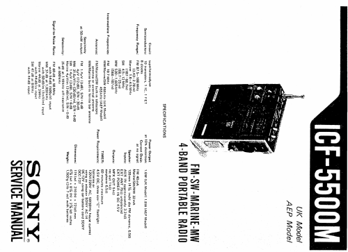
There are two versions: UK and AEP:
- UK is 468kHz AM IF and 1.6W audio at 10% distortion.
- AEP is 455kHZ AM IF and 1.8W audio at 10% distortion.
Shortwave coverage 1,6 - 4,5 and 4,5 - 12 MHz.
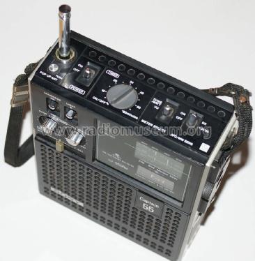
VHF uses separate L.O. and mixer with JFET RF pre-amp (only band pass tuned on input).
MW Local/DX switch varies gain at first AM IF.
Three 3.5mm 2 pole jacks allow conversion to stereo, using existing audio amp and speaker as one channel (Aux In). The L+R level on MPX out is about the same as required by Aux In. The third jack socket provides DC power for stereo MPX decoder.
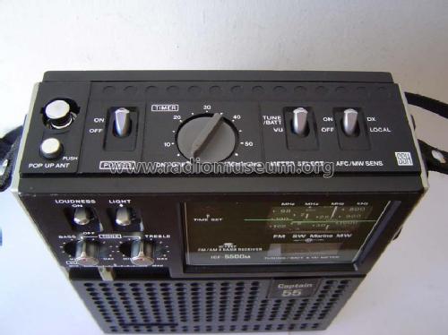
The Main On/Off and the 60 minute mechanical timer are cross wired to give up to 60 minutes running time, or up to 60 minutes before the radio turns on.
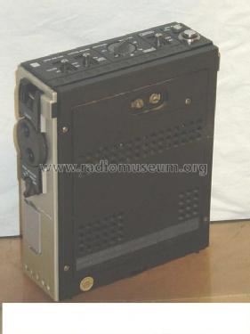
The rear external aerial terminals connect via 10pF capacitor to the whip (and direct to 0V/chassis) used of for VHF or main Shortwave band. The Marine band uses a separate winding / coil on the same ferrite rod used for MW (Broadcast) as well as the external aerial.
The model is very similar to the Sky Sensor 5500 (1973, Japanese market). Some markets had the Sony ICF-5500 which includes a low power VHF-FM transmitter and microphone.
The Marine band covers the USA extended Broadcast AM band, as well as 90m and 120m tropical bands.
- Net weight (2.2 lb = 1 kg)
- 1.5 kg / 3 lb 4.9 oz (3.304 lb)
- Source of data
- - - Data from my own collection
- Mentioned in
- Alles über die Sony Weltempfänger, R. Lichte
- Literature/Schematics (1)
- Funk-Technik (FT) (11/1973, S. 377 / Werbeanzeige)
- Literature/Schematics (2)
- Trader Service Sheet 3209 / 1976
- Author
- Model page created by Peter Böhm. See "Data change" for further contributors.
- Other Models
-
Here you find 4077 models, 3934 with images and 977 with schematics for wireless sets etc. In French: TSF for Télégraphie sans fil.
All listed radios etc. from Sony Corporation; Tokyo
Collections
The model Captain 55 is part of the collections of the following members.
- Peter Böhm (D)
- Martin Bösch (CH)
- Nikolai Galak (UA)
- Salvador Galan-Ocaña (E)
- Nico Jacobsen (D)
- Ervé Leclercq (B)
- Sofronios Markidis (GR)
- Dieter Michel (D)
- Zlatan Mumlek (HR)
- Jean-Louis Pelletier (F)
- Paolo Rebecchi (E)
- Felix Schaffhauser (CH)
- Dieter Schulte-Kulkmann (D)
- Michael Watterson (IRL)
- Eckhard Wegner (D)
- Axel Woebker (D)
Forum contributions about this model: Sony Corporation;: Captain 55 ICF-5500M
Threads: 5 | Posts: 12
The control panel suggests that the meter is VU (audio level) or Tune/Batt. However I can't see by schematic or operation how it shows battery condition. A clue may be that the meter rests at right with power off or batteries removed. I'm not convinced the schematic is correct on meter wiring, looking at how VU works. Or I'm confused.
Michael Watterson, 19.Jan.16
The 1974 UK service manual doesn't seem to mention this, or I may have missed it.
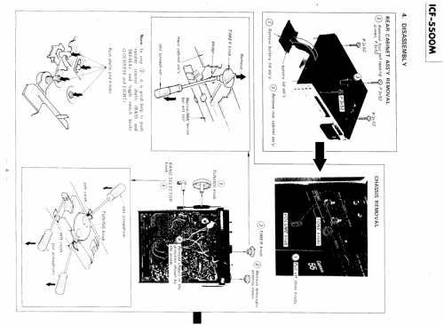
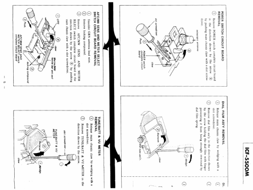
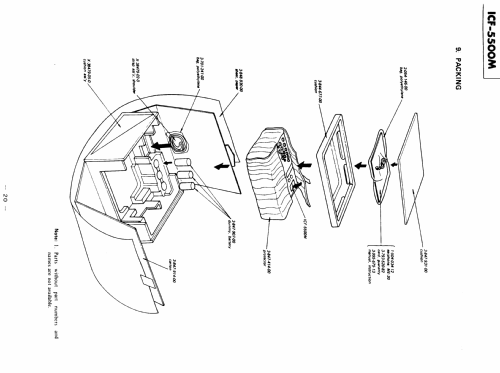
- Remove the batteries and carefully prise off all knobs.
- Take out the four rear screws
- Lift chassis out from battery end. It comes out easily especially if all top switches are at off.
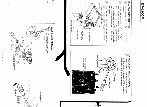
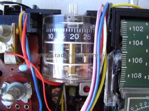
- Tune past 530KHz till end of scale. There is a small white line on the scale film. Align with slot on mount by gently disengaging the scale film drive cog.
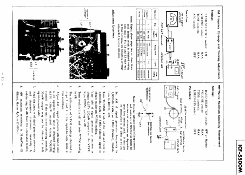
Make sure on VHF alignment that the AFC is OFF and if using a cheap "MP3 FM" transmitter, don't feed audio to it.
There are two slots, one for VHF scale on left and one for AM on the right to show tuned frequency. The VU meter pops out to reveal L3, RF VHF trimmer (88MHz). On my model the CT8 (108MHz ) is beside it but accessed from PCB side. The service manual specifies 86.5 MHz and 109.5MHz as tuning points. If you are using a cheap MP3 player FM TX, use 88MHz (or 87.5MHz) and 107.50MHz (or 108MHz) instead. The Local Oscillator is CT7 (108MHz) and L6 (88MHz). L6 seems to be tricky. Use a plastic tool.
Otherwise follow the service manual. Email me if I forget to upload the rest of it.
As an aside, the power consumption is actually less than a TENTH of a 21st Century DAB radio (30 hours on 4 x Alkaline D cells). It should manage over 150 hours on 3 x Alkaline C cells.
Michael Watterson, 17.Jan.16
The Sony Captain 55 is powered by only 3 baby cells. The battery current is 50 - 100 mA at normal listening volume. This is a rather large current. Above that, the minimum voltage that the radio needs, in order to function normally, is about 3,8 V. This means that the radio needs new batteries at a point where the batteries are not quite empty (considering that normal equipment can run on lower voltages).
Because of this power consumption I decided to use rechargable batteries.
At the time I bought this radio, the best choice was NiCads. But 3 NiCads deliver only 3 * 1,4 V = 4,2 V at max, right after charging. This voltage lowers rather quickly below 3,8 V. Not enough. So I put in a fourth NiCad in the radio itself, right below the timer. Some plastic had to be removed to make some space there. After that, the voltage was a nice 4,4 V (battery almost empty) to almost 6 V (battery full). The radio can use that extra voltage well and functions better. And, very important: the radio is not harmed by this 6 V.
A miniature electronic circuit was designed and installed in the radio (!) to watch the battery voltage. Below 4,4 V this electronic switch switched off the whole radio. Doing this, the NiCads were protected against too low battery voltage during use, and therefore they live much longer. I will put the schematic on this forum later.
To be able to charge the NiCad battery, the "power in" connector was modified also. This connector was connected directly to the battery.
Pieter de Jong, 14.Sep.09
Versions of the ICF-5500M exist that have a function of short range FM transmitter/receiver. It can be compared to a CB transceiver. The little plate that says "Captain 55" is not there, but instead there is a push-down switch that switches the radio in FM transmitter mode.
It seems that this was popular in Japan.
Pieter de Jong, 14.Sep.09
This set seems to exist in AM IF 455 kHz and 468 kHz (maybe UK ?) variants, see images of typeplates.
Kind regards Martin Boesch
Martin Bösch, 08.Dec.08