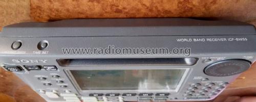
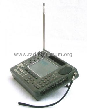
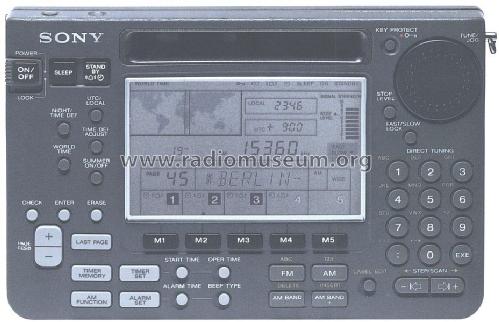
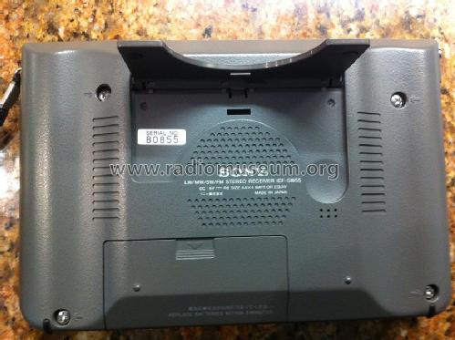
LW / MW / SW / FM Stereo Receiver ICF-SW55
Sony Corporation; Tokyo
- País
- Japon
- Fabricante / Marca
- Sony Corporation; Tokyo
- Año
- 1991
- Categoría
- Radio - o Sintonizador pasado WW2
- Radiomuseum.org ID
- 74813


Kaunas Lithuania

Weltempfänger Sony ICF-SW55

Kaunas Lithuania
Kaunas Lithuania

Kaunas Lithuania


Haga clic en la miniatura esquemática para solicitarlo como documento gratuito.
- Numero de transistores
- Hay semiconductores.
- Semiconductores
- Principio principal
- Superheterodino doble o triple conversión; ZF/IF 55845/455 kHz
- Gama de ondas
- OM, OL, OC y FM
- Tensión de funcionamiento
- Pilas + jack (etc.) para alimentación externa. / AA: 4 x 1.5 / DC 6 Volt
- Altavoz
- Altavoz dinámico (de imán permanente)
- Potencia de salida
- 0.4 W (max.)
- Material
- Plástico moderno (Nunca bakelita o catalina)
- de Radiomuseum.org
- Modelo: LW / MW / SW / FM Stereo Receiver ICF-SW55 - Sony Corporation; Tokyo
- Forma
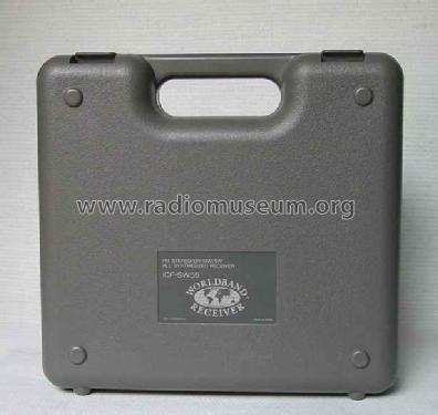
- Portátil > 20 cm (sin la necesidad de una red)
- Ancho, altura, profundidad
- 194 x 127 x 39 mm / 7.6 x 5 x 1.5 inch
- Anotaciones
-
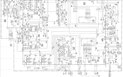
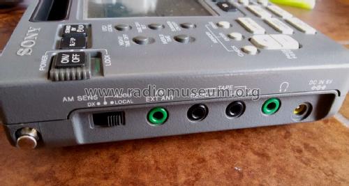
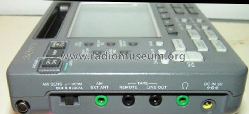
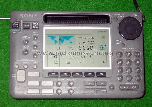
Coverage 150 - 30000 kHz (german model 150 - 26100 kHz), AM, SSB(USB/LSB), digital frequency readout, frequency keypad entry, 125 alphanumeric memories. World time clock, sleep timer and alarm. Ext. power jack: DC 6 V (Polarity uses Positive on the center pin of the DC plug).
- Peso neto
- 0.9 kg / 1 lb 15.7 oz (1.982 lb)
- Precio durante el primer año
- 626.00 DM
- Ext. procedencia de los datos
- R. Lichte
- Mencionado en
- -- Original-techn. papers.
- Autor
- Modelo creado por Martin Bösch. Ver en "Modificar Ficha" los participantes posteriores.
- Otros modelos
-
Donde encontrará 4071 modelos, 3928 con imágenes y 976 con esquemas.
Ir al listado general de Sony Corporation; Tokyo
Colecciones
El modelo LW / MW / SW / FM Stereo Receiver es parte de las colecciones de los siguientes miembros.
Contribuciones en el Foro acerca de este modelo: Sony Corporation;: LW / MW / SW / FM Stereo Receiver ICF-SW55
Hilos: 1 | Mensajes: 4
Got this radio as not working. Symptom is the CAL message at power ON not being cleared and the radio turns off.
This CAL issue is one of the common failures found in this model. After reading the SONY documentation and several Internet shared information on this issue, namely from Fabio from Antica Radio, I had some insight on the subject.
The user guide mentions that "CAL appears when power is supplied, or when calibration adjustment is made". When inserting new batteries, the CAL msg displays for a couple of seconds. The radio will complete the CAL procedure and enters normal operation defaulting to 150 kHz.
The CAL function can also be called manually by pressing AM Function and then Memory 1.
Another one even more common failure relates to defective electrolytic capacitors that results in several symptoms like strange audio noises or no sound at all.
The electrolytic capacitors tend to leak the electrolytes that spread over the other PCB components, resulting in all sort of problems. By removing the failed capacitors, cleaning both sides of the PCB with isopropyl alcohol, and installing new capacitors of the same type, will usually fix these issues. Some prefer to replace the old electrolytic capacitors with tantalum ones. I prefer to install the same type from modern, fresh batches.
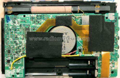
After opening my radio, I immediately noticed two things.
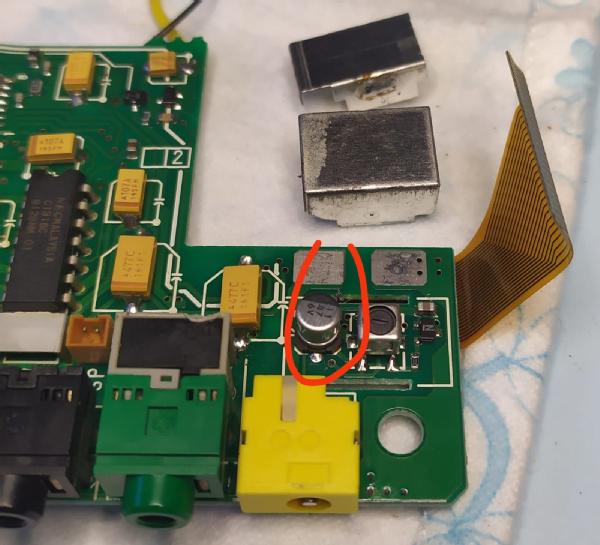
Someone has been inside before, and had replaced all electrolytic capacitors by tantalum equivalents. The job looked nice with clean solder joints. All of them? Well, not exactly. One cap (C236) in the DC-DC converter, hidden inside the metal shield, was forgoten.
The other thing was a burnt transistor (Q53) acting as a 6V switch to the audio power amp (IC7).
So I didn't think too much about it, just replaced the burt transistor (Q53) with a SS8550-SMD that is close in specs to the original. Applying 6V DC from my power supply gave me a few amps of current peak and burning smell. Nice.
I removed Q53 again, and applied power to see if the radio would pass the CAL phase. No luck, as the radio keeps powering off after a few seconds after CAL message.
So I had two different issues, one for CAL and another for the audio stage.It turned out that both issues were related.
The IC 7 audio IC didn't look in short at pin 12 and GND. Something else was causing the short on the B+ line. It must be the 470uF bypass capacitor C195. Then I realized that that nice replacement of the defective electrolytic capacitors by tantalum ones had gone wrong. All tantalum caps were installed with reverse polarity!
I removed the tantalum caps and threw them away, as they were all more or less damaged by applying reverse polarity voltage.While doing so, a terrible smell of burn electrolytes told me that the PCB was not properly cleaned when replacing the original caps with these tantalums. So I used IPA to have a brief cleaning of the PCB, before installing new fresh batch electrolytic caps.
That fixed the audio issue but the CAL message issue kept popping up. Using an oscilloscope to check the signal at pin 6 of the PLL (IC8) told me that there was no oscillation at all.
This time I knew the cause. Just above this IC8 is another infamous electrolytic cap that surely had leaked around and contaminated the trimmer cap (CT6). By removing CT6 and measuring it for DC resistance, I got around 300KR to 3MR depending on the position of the rotor.
Powering up the radio I finally saw the CAL(ibrating) message completing and the radio displayed the 150kHz RF band with normal RF noise.
Replaced TC6 with a similar 10pF trimmer. Could not adjust the osc frequency to the specified 6.275MHz as my current oscilloscope use just two decimal places giving me alternating values between 6.27 and 6.28MHz.
Took the opportunity to replace the MCU 0.22F/5.5V supercap (C903) as these things tend to deteriorate as well.
I am enjoying my classic Sony radio while writing these lines.
Hidden cap inside the metal shield of the DC-DC converter.
Burnt transistor switch for audio power amp.

Defective components. Supercap was weak. Tantalum caps and transistor were victim of wrong install. Trimmer cap was a genuine victim of the original issue of leaking electrolytic caps.

Jose Mesquita, 26.Oct.23