Stenode Radiostat
Stenode Corp. of America; Long Island, NY
- País
- Estados Unidos
- Fabricante / Marca
- Stenode Corp. of America; Long Island, NY
- Año
- 1930
- Categoría
- Radio - o Sintonizador pasado WW2
- Radiomuseum.org ID
- 59995


Haga clic en la miniatura esquemática para solicitarlo como documento gratuito.
- Numero de valvulas
- 10
- Numero de transistores
- Semiconductores
- Stenode
- Principio principal
- Superheterodino en general; 3 Etapas de AF
- Gama de ondas
- OM (onda media) solamente
- Tensión de funcionamiento
- Baterías recargables o pilas
- Altavoz
- -Altavoz incorporado, sistema desconocido.
- Material
- Madera
- de Radiomuseum.org
- Modelo: Stenode Radiostat - Stenode Corp. of America; Long
- Forma
- Consola baja, patas más cortas del 50%.
- Anotaciones
-
This radio, hailing from England, presents a curious puzzle. Though originating across the pond, its schematic can be found in Rider's Volume 1, while the "Radio Collector's Guide 1921-1932" miscategorizes it as a 1926 TRF (totally inaccurate!).
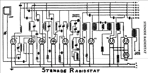
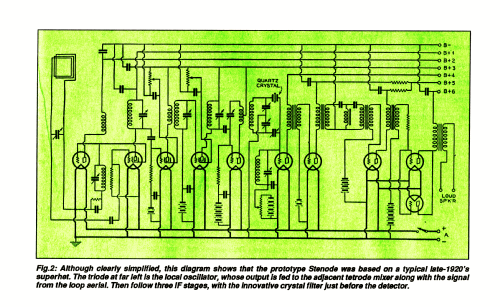
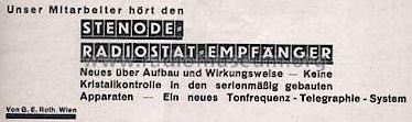
Adding to the mystery, an October 1930 "Radio News" article lauded it as a "revolutionary new design" destined to reshape radio's future, featuring a unique superheterodyne circuit with a "Stenode" element. This invention by Dr. James Robinson of the Receptite Company, a quartz crystal filter before the second detector, promised ultra-high selectivity ideal for continuous wave applications, but not ideal for broadcast reception.
However, the hype quickly faded over the following months, hinting at hidden truths behind the initial fanfare. Notably, the model boasts a push-pull audio output stage, suggesting a potential departure from the standard tube-based Stenode toward a discrete component array.
While we list its tubes for reference, the non-standard "Stenode" component remains excluded, blurring the lines of what truly constitutes a "radio tube."
- Ext. procedencia de los datos
- Ernst Erb
- Procedencia de los datos
- Radio Collector`s Guide 1921-1932
- Referencia esquema
- Rider's Perpetual, Volume 1 = 1931/1934 (for 1919-1931)
- Mencionado en
- Funkgeschichte der GFGF (266/2022 S.246ff.)
- Otros modelos
-
Donde encontrará 1 modelos, 1 con imágenes y 1 con esquemas.
Ir al listado general de Stenode Corp. of America; Long Island, NY
Literatura
El modelo Stenode Radiostat está documentado en la siguiente literatura.
Contribuciones en el Foro acerca de este modelo: Stenode Corp. of: Stenode Radiostat
Hilos: 1 | Mensajes: 2
1930 the quartz crystal filter as such is not new: In Walter Cady's book "Piezoelectricity" (originally published by McGraw-Hill in 1946; 2nd revised ed. Dover, 1964) is indicated that he first proposed the idea of using a crystal in a filter in 1921. He referred to his Proc. IRE article, and his patent US1450246, filed Jan 28 1920, granted April 23 1923. James Lamb (inventor of the "Lamb noise silencer") made the use of quartz crystal filters popular for amateurs, beginning with his article "Short Wave selectivity to match present conditions" in August 1932 QST (and Aug 1932, Nov 1933, May 1935, Apr 1937 and June 1937). There were many more inventions how to use crystals, like Warren Mason introduced the lattice filter in 1929 (to improove Espenschied's filters) - but was popular only much later after WW2.
Below is an article about the "Stenode" circuit written by the inventor, Dr. James Robinson, radio engineer of the "Receptite Company of London", England. The invention was based on a quartz crystal filter circuit (piezoelectric unit) in the intermediate frequency amplifier (IF stage) just before 2nd detection in a superhet. This to balance out all frequencies except signals at the crystal frequency, giving very high selectivity.
Robinson was granted at least four US patents for his work, ie US1821032, US1821033, US1898895 and US1908558. All four patents were filed between 1929 and 1930, and all four show some form of a center-tapped transformer crystal filter circuit. Robinson published his work in the USA during a lecture tour in 1930, and its potential use in amateur radio was first recognized by American engineers and amateurs.
In the US, "Stenode Corporation of America" (Hempstead Gardens, Long Island, NY)" published at least four papers/books in 1931: "The Stenode" (a paper delivered by Dr. James Robinson before the Radio Club of America), "Full instructions for building the Stenode w/5 blueprints", "Quartz Crystals in Radio Receiving Circuits" and "Engineering data book for the Stenode" probably the same as "Engineering Bulletin Number One", a 23 page booklet giving a general outline. By the way: "The Encylopaedia Britannica" does not mention the word.
An other text is: R. R. Batcher. Applications of piezo-electric crystals to receivers.
Electronics, 3, 57-58; August, 1931: "The piezo-crystal bridge circuit as used in the Stenode is analyzed. A simple relation between the factors which govern the response of the bridge as a whole is developed."
But also the German "Funkschau" printed 1931 something about the Stenode-Radiostat - on page 390.
In "Short Wave Craft" for October 1932 one finds mentioned the "crystal controlled Stenode" on page 332 on an article about "Band Spreading" by James Millen. In an article in the October 1933 issue of "Radio", title "Single-Signal Receiver for Byrd Expedition" McMurdo Silver writes: "Probably the first use of the quartz crystal resonator for extreme selectivity in radio receiver design that came to popular knowledge was Dr. Robinson's Stenode Radiostat circuit. Unfortunately, this system contributed greatly to "apparent" selectivity (difficulty of tuning), but very little to "actual" selectivity (elimination of interference), except in almost direct proportion to loss of fidelity. Time seems to have proven that a crystal resonator has no place in a high quality broadcast receiver. But for C.W. code reception, it has a very definite place ..."
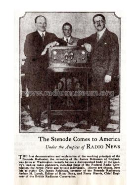
In 1930 the Stenode principle caused quite some interest in the USA: The very popular "Radio News" (October 1930) found it to be a "revolutionary new radio design which was to completely alter the future of radio". They featured this revolutionary design in following issues (like 1931, page 590ff), but soon it was clear that it did not have advantages for broadcast receivers and there interest quickly died away.
By the way: In the radio adventure story “The Shadow” a "Stenode radio-stat" could indicate the radio station on the map at the top of the receiver. This has nothing to do with our Stenode Radiostat nor the same name of plants. I don't think this text in Spanish is correct in the book "Historia y técnica ..." from Juan Juliá Enrich, Barcelona: "1921: Robson obtiene la patente francesa número 679.925 sobre un sistema de receptión ultra-sensitivo baseado en las propriedades de estabilidad del cristal de courzo, conocido con el nombre de Stenode-Radiostat."
This text below has been OCR digitalized by the guest Bengt Grahn from Sweden, now being a member. He asked me to publish it and he has scanned it from the journal "Newnes complete wireless" which was published quite later than in 1930 (date not known). It is most probably just a copy of an article which was published many years before.
THE STENODE
By J. Robinson, D.Sc., Ph.D., M.I.E.E.
A very interesting method for making scientific progress is to investigate the behaviour of a particular device under a variety of circumstances. Variations occur as the conditions change, and it is always useful to vary the conditions in the widest possible manner. An example of this is given by the electrical resistance of metals at various temperatures, the general case being for the resistance to rise and fall as the temperature rises or falls. As it would be highly desirable to have a material whose resistance is exceedingly low, tests were made at the lowest possible temperature, and the resistance was found to go near the vanishing point.
The Stenode is another application of the method for carrying the investigation of physical properties to the limit, and in this case the selectivity of wireless devices was pushed as far as possible. Selectivity is the property of a circuit which enables it to receive one frequency better than others, and as the selectivity is increased we are enabled to receive a narrow band of frequencies with very little effect from all others.
When highly selective circuits have not been used
Before the Stenode was introduced it was possible to obtain highly selective circuits, but they were not employed for the reception of wireless signals such as broadcasting, because they were considered unsuitable for this purpose. Actually, it was generally believed that if selectivity were made very high the portion of the signal which conveys the intelligence would not be received. It was believed that when we use such a circuit we would receive, in place of the variable waves, which are sent out from a transmitter, only continuous waves, and that the variable portion, which conveys the intelligence, would not be received, Put into technical language, a transmitter of telephony sends out waves whose frequency is constant, and whose amplitude is also constant when sending no intelligence. The waves are made useful for conveying intelligence by making the amplitude vary, or by modulating the waves. Fig. 1a shows continuous waves and Fig. 1b the modulated waves.

Opinion was general that if a very highly selective circuit was employed we should obtain the same result whether we received continuous or modulated waves, and thus it was thought to be useless to employ such highly selective circuits for receiving broadcasting.
The sideband theory
This difficulty will perhaps be understood more clearly by reference to the theory of telephony, which has become universally accepted. This theory is called the Sideband Theory, and is to the effect that any series, of modulated waves as in Fig. Ib, can be represented as the sum of a number of continuous waves of the same nature, as those of Fig. Ia, but with different frequencies and with different amplitudes.
-- and what it is
Thus , if we transmit one musical note of frequency 5oo c/s., which is a note about an octave higher than middle "C" on the piano, and if the frequency of the wireless transmitter is 1,ooo,ooo c/s., the sideband theory states that this is the same as if we transmitted three series of continuous waves simultaneously, of frequencies, 999,500 c/s., 1,ooo,ooo c/s., and 1,ooo,5oo c/s., the centre frequency corresponding to carrier waves and the two outside frequencies to the sidebands. When we transmit a passage of music, notes are employed from about 3o c/s. to 5,ooo c/s., or even to 1o,ooo c/s., and thus, if we assume that 5,ooo c/s. Is the highest note, we have many continuous waves transmitted, ranging from 995,ooo c/s. to 1,oo5,ooo c/s.
Why circuits of very high selectivity were considered useless

As modulated waves can thus be considered as a series of continuous waves of different frequency, and in this case extending over a frequency range of 1o,ooo c/s., it appeared useless to employ very high selectivity, for this would imply that we would only receive frequencies, say, from 1,ooo,ooo to 1,ooo,1oo c/s. if we had a circuit so selective that it gave appreciable response only to waves whose frequencies are not more than 5o c/s, away. It thus became a recognised point of view that if we employed a circuit so selective as this it would receive only the carrier waves and cut off the waves, and would cut out the sidebands. As the latter are essential to the correct reception of the signals, we thus see what a stumbling block there was in the path when anyone wanted to increase the selectivity for telephony purposes. A telephone transmission could thus be represented, as in Fig. 2, with carrier waves of frequency "n," and with two sets of sidebands symmetrically placed with regard to the carrier. In order to receive this transmission, we should therefore have a receiver which will receive the sidebands "c" and "c1" equally as well as the carrier. Thus, as these extreme sidebands are 1o,ooo c/s apart, we must have the resonance curve of our receiver something like A, B, C, D, E, of Fig. 2.
How the stenode works
The Stenode, however, employs a resonance curve something 1ihe X, C, Y, and we must now consider more closely how it was possible to arrange for correct reception with such a highly selective circuit, particularly where theory pointed to the fact that such a circuit would give us nothing but the carrier waves, which are unintelligible.
Some of the properties of a highly selective circuit
The reception of modulated waves by a circuit of very high selectivity will be better understood after we have examined some of the properties of a selective circuit. A typical tuned circuit consists of an inductance and a condenser connected in parallel. There are three controlling factors in such a circuit, the inductance, L, the capacity, C, and the resistance, R. The frequency depends principally on the values of L and C, whilst the resistance, R, controls other features.
Damping depends on amount of resistance
If the resistance, R, were zero, the tuned circuit would continue to oscillate for ever once it had been excited in any way. The energy would alternate between the inductance and the condenser at regular intervals, there being nothing to stop it. However, it is not easy to obtain the condition where the resistance is zero, and when resistance is present the electrical energy is dissipated in the form of heat and in other ways, thus producing a gradual diminution of energy resulting in the vibrations being damped, so that each is lower than the preceding. The damping thus depends on the amount of resistance.

In wireless the tuned circuit of Fig. 3 is excited by incoming waves of a frequency identical with that of the circuit, and again by waves whose frequency is very nearly the same. For waves of the same frequency , n, we again find the resistance, R, having a large influence, and if R is zero we would have the succeeding incoming vibrations adding energy to the circuit, and this process would go on indefinitely, thus ultimately giving us an exceedingly large amplitude of vibration. Here again we see the significance of the resistance, for it places a definite limit on the maximum amplitude, and we have the conditions that for a large value of resistance or damping we obtain a comparatively small response, and this occurs after a few incoming vibrations. For a low value of resistance or damping a longer time is required to reach the maximum amplitude, but ultimately a high value is reached. These results are summarised in Fig. 4.

Time required to build up to a maximum
Suppose waves of constant amplitude arrive for a definite time given by PQ, the actual amplitudes of vibration for two circuits at different intervals of time shown, the curve 0ABC giving the result for a high value of damping, and 0A'B'C' for low damping. The maximum amplitudes MA and M'A' are inversely proportional to the resistance or damping. The time required to build up to the maximum increases as the damping falls, and again the time required to die down to zero also increases as the damping falls.
What happens in a highly damped circuit?
With a highly damped circuit as in 0ABC, we thus have a condition in which the receiver rapidly comes to rest after it has once been excited, thus becoming ready for the next signal. In other words. Such a receiver follows the variations of incoming signals fairly faithfully. The low damped circuit 0A'B'C', however, requires a long time to build up and to die down, and it thus does not follow the incoming signals faithfully. When a series of telegraphic signals arrive, the highly damped receiver rises to its maximum and goes back to zero for each signal, as shown in Fig. 5. For incoming signals a, b, c, d, the highly damped receiver responds as at 0AB, CDE, FGI, etc., each signal being distinct.
However, the low-damped circuit never comes to rest under these conditions, and the amplitude follows the curve 0A'B'D'E'G'K'L'M'. It thus appeared as if we must be restricted to highly damped circuits in order to follow incoming signals, and thus that we could not obtain the benefits of high selectivity.
Amplitude rises and falls with the incoming signals
A closer examination shows, however, that the selective receiver follows the incoming signals after some sort of fashion, and that, although it is vibrating all the time, its amplitude increases whenever a signal arrives, as at B'D', or E'G', or K'L', and that its amplitude falls when the incoming signal ceases, as at A'B', or D'E', etc. Thus, although the receiver is never at rest, its amplitude rises and falls with the incoming signals. Thus the signals are represented, and the Stenode makes use of them.
Actually there is a large amplitude of oscillation in this receiver, and a comparatively small percentage change for each signal, but the actual rise and fall is about equivalent to the whole rise and fall for the highly damped circuit. In other words, the vertical fall from G' to K' is approximately the same as that from G to I, and thus the actual signal strength is about the same. We can thus employ circuits of high selectivity to receive signals and, in fact, it is immaterial whether these are of the telephonic or telegraphic type. This receiver has usually a large amplitude of oscillation, and its amplitude rises and falls with the incoming signals.

Effect of modulation frequency
This is, however, not by any means the whole story, and we find that the amount of rise and fall of the amplitude of the receiver depends on the modulation frequency. This can be seen from a telegraphic example, where we consider the effect of high and low speed signalling. In Fig. 6 the low- and high-speed incoming signals are shown. The response in a highly selective receiver which has already built up to its maximum amplitude is shown as ABCDEFG for the low-speed signals abc, and as A'B'C'D'E'F'G' for the high-speed signals defghi.

The actual signals received in the two cases are given by the changes of amplitude, and for the low-speed signals the receiver has a comparatively long time to die down, thus giving the signals BC, which are stronger than the high-speed signals.
Signal strength inversely proportional to the modulation frequency
There is thus a very important effect that the strength of signal diminishes as the signalling speed or as the modulation frequency increases. This has been accurately calculated, and for very highly selective circuits it is found that the signal strength is inversely proportional to the modulation frequency. The formula for this effect is comprehensive and shows how the signal strength depends on the selectivity of the circuit, which is defined by the damping factor, and, further, how it depends on the frequency of the carrier waves and on the modulation frequency. It is actually shown how the percentage modulation of the incoming signals (m) is diminished to a value m', when the damping factor is δ and when the carrier frequency is n and the modulation frequency is p. The formula is
m' = m * (n/p) * ( δ/2*π).
Reinstating the modulation correctly
Having shown how all modulation frequencies are accepted by a circuit, no matter how high its selectivity may be, but that these modulations are not present in their correct proportions, it is necessary to provide some means for reinstating the modulation correctly. The signal strength being inversely proportional to the modulation frequency, it is necessary to introduce some device which will allow the higher modulations to pass more easily than the lower modulations, and a convenient way of doing this is to design a low-frequency amplifier which amplifies high frequencies more than low frequencies. In fact, for very high selectivity we must amplify strictly proportionally to the frequency.
Thus, finally, we have a receiver which consists essentially of a highly selective circuit, with a detector, followed by a low-frequency amplifier which amplifies high notes more than low.
Tuning forks and quartz crystals
Some interesting features are introduced in carrying out these ideas in practice, and up to date the best results have been obtained by using the superheterodyne principle. Amongst the most selective devices known are tuning forks and piezoelectric quartz crystals. With a tuning fork it is possible to obtain a resonance curve so sharp that when we are one or two cycles p.s. out of tune the response is only a few per cent of that for resonance. However, measured in actual cycles distant from resonance, we find that, as the frequency of the fork or the crystal increases, the apparent selectivity diminishes.
Thus for a quartz crystal of a frequency of 1o,ooo c/s. the response, when we are 1oo c/s. out of tune, is only a few per cent of that at resonance. A crystal of frequency 5o,ooo c/s. or 1oo,ooo c/s. is quite practical for broadcasting purposes, and obviously it has exceedingly large selectivity. However, for broadcasting purposes we have a 1arge number of transmitters with frequencies varying from about 16o,ooo c/s. to about 1,5oo,ooo c/s., and, unfortunately, the frequency of each crystal is fixed.
Where to Place the Quartz Crystal
Thus, practically, we find it best to employ the superheterodyne principle, placing the quartz crystal in the intermediate stage and then, after the second detector, to use a corrected amplifier.
Other ways of obtaining the High Selectivity
Instead of a quartz crystal the high selectivity in the intermediate stage can be obtained in other ways, but it is not easy to approach the quartz selectivity by ordinary wireless methods. However, by a series of tuned circuits, it is possible tȯ obtain a resonance curve such that when we are 5,oo c/s. away from resonance the response is less than one per cent. of that at resonance. Stenodes made on this principle give excellent results.
The Autotone
The superheterodyne principle lends itself to this purpose of high selectivity, because we are concerned only with one frequency, the intermediate frequency. If we depart from the superheterodyne principle, we have the problem of maintaining the selectivity high when the frequency is changed. This introduces problems which naturally are capable of solution, and, in fact, receivers like the Autotone have already been described in which the selectivity is obtained by means of reaction.
Results Obtained with the Stenode
The practical results obtained by the Stenode have excited great interest, and they have brought forward much theoretical discussion. For broadcasting purposes, neighbouring channels are received with scarcely a trace of interference, even when the conditions are very severe, such as the reception of a weak distant station when geographically near to a neighbouring transmitter. Stations have frequencies allocated to them in such a manner that, as far as possible, they are never closer together than 9,ooo c/s. However, there are so many stations that many of them are closer together than this. Practical Stenodes have so far been designed to give uniform reproduction for all tones up to 5,ooo c/s., and even when transmitters are only 5,ooo c/s. apart there is scarcely a trace of interference between them. One example of this in the broadcasting range is that of the two transmissions from the Eiffel Tower and from Warsaw, whose frequencies are 5,ooo c/s. apart.
Because of these remarkable results, many highly theoretical treatises have appeared recently which have given special attention to the types of interference which occur between neighbouring stations, and showing how the Stenode completely eliminates some of them. Actually a Government committee was set up to investigate the problem, and the results of their investigations have recently been published as Radio Research Report No. I2, under the title "A Theoretical and Experimental Investigation of High Selectivity Tone Corrected Circuits." To enter into this question would, however, require much more space than has been allotted to me.
There remains here only one further remark, which is: that the advantages of high selectivity are not restricted to broadcasting, and there are many other applications, such as the multiplication of the words per minute that can be sent telegraphically over wires.
Ernst Erb, 19.Feb.09