Sterling Type 54A Transmitter
Sterling Telephone & Electric Co. Ltd.; London
- Country
- Great Britain (UK)
- Manufacturer / Brand
- Sterling Telephone & Electric Co. Ltd.; London
- Year
- 1916
- Category
- Commercial Transmitter (TX not Transceiver)
- Radiomuseum.org ID
- 276045
Click on the schematic thumbnail to request the schematic as a free document.
- Main principle
- Transmitter
- Wave bands
- Wave Bands given in the notes.
- Power type and voltage
- Storage and/or dry batteries / 24 Volt
- Loudspeaker
- - - No sound reproduction output.
- Material
- Metal case
- from Radiomuseum.org
- Model: Sterling Type 54A Transmitter - Sterling Telephone & Electric
- Shape
- Chassis only or for «building in»
- Notes
-
The Sterling Type 54A Transmitter was used on long range patrol aircraft and night bombers.
The input to the spark transmitter was 120 Watt and powered by an alternator driven by a wind screw placed in the slipstream of the propeller. The frequency range was from 200-335 & 500-600 metres. This achieved a working range of 80km.
It was powered by an alternator driven by a wind screw placed in the slipstream of the propeller. The input power was 120 Watts at 24V and powered from a 24B battery.
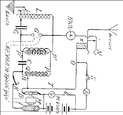
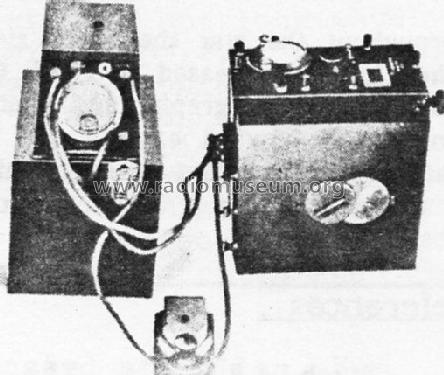
A motor driven rotary interrupter, (“I” on schematic) with a tuned transformer “P”,”Q”,”R”,”C” gave improved efficiency. A socket “N” was the aerial connection and an insulating block “X” switched off the motor when the receiving plug was inserted. The spark gap could be ventilated by means of an air blast from the motor. A set consisted of three units; Transmitter, rotary interrupter and accumulators.
- Net weight (2.2 lb = 1 kg)
- 20 kg / 44 lb 0.8 oz (44.053 lb)
- Mentioned in
- HRSA Radiowaves, No. 23 January 1988
- Author
- Model page created by Gary Cowans. See "Data change" for further contributors.
- Other Models
-
Here you find 39 models, 33 with images and 6 with schematics for wireless sets etc. In French: TSF for Télégraphie sans fil.
All listed radios etc. from Sterling Telephone & Electric Co. Ltd.; London
Literature
The model Sterling Type 54A Transmitter is documented in the following literature.