All-Wave Signal-Generator 65B
Taylor Electrical Instruments Ltd.; Slough, Dover
- País
- Gran Bretaña (GB)
- Fabricante / Marca
- Taylor Electrical Instruments Ltd.; Slough, Dover
- Año
- 1942–1948 ?
- Categoría
- Aparato de medida y servicio (Equipo de laboratorio).
- Radiomuseum.org ID
- 104007
-- Original-Prospect

Haga clic en la miniatura esquemática para solicitarlo como documento gratuito.
- Numero de valvulas
- 3
- Gama de ondas
- Bandas de recepción puestas en notas.
- Tensión de funcionamiento
- Red: Corriente alterna (CA, Inglés = AC) / 110; 210; 240 Volt
- Altavoz
- - - No hay salida de sonido.
- Material
- Metálico
- de Radiomuseum.org
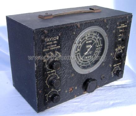
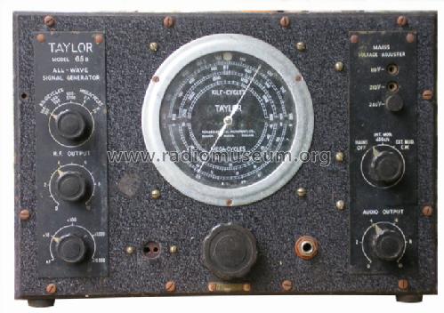
- Modelo: All-Wave Signal-Generator 65B - Taylor Electrical Instruments
- Forma
- Sobremesa apaisado (tamaño grande).
- Ancho, altura, profundidad
- 307 x 207 x 154 mm / 12.1 x 8.1 x 6.1 inch
- Anotaciones
- Signal-Generator, coverage from 100 kHz to 23 MHz, plus harmonics to 46 MHz, in 6 ranges, built-in 400 Hz audio generator. Two pin connector is RF out (larger pin Earth)
Jack socket is audio out or in. One 6J5 is RF osc and the other optional 400Hz audio
- Peso neto
- 4.5 kg / 9 lb 14.6 oz (9.912 lb)
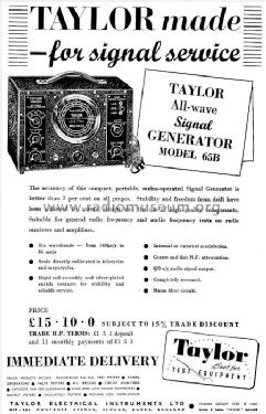
- Precio durante el primer año
- 15.50 GBP
- Mencionado en
- -- Original prospect or advert
- Autor
- Modelo creado por un miembro de A. Ver en "Modificar Ficha" los participantes posteriores.
- Otros modelos
-
Donde encontrará 44 modelos, 43 con imágenes y 16 con esquemas.
Ir al listado general de Taylor Electrical Instruments Ltd.; Slough, Dover
Colecciones
El modelo All-Wave Signal-Generator es parte de las colecciones de los siguientes miembros.
Museos
El modelo All-Wave Signal-Generator se puede ver en los siguientes museos.
Contribuciones en el Foro acerca de este modelo: Taylor Electrical: All-Wave Signal-Generator 65B
Hilos: 2 | Mensajes: 2
I found an Instruction manual (Search for "Thevalvepage"). The manual has a basic schematic but without any values. Another feature of the manual is the three Appendixes:
1: Adjustment of Receivers and Amplfiers
2: Frequency Conversion Tables
3: Intermediate Frequencies (Originally 14 pages of IF for Radio Sets of Radio up to 1940s).
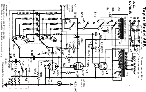
All designations are according to my annotation of schematic
Circuit Description
The mains connects to on/off switch on the Modulation Int/Ext control and voltage selector via a filter C1 ... C4 & L1, L2. The switch and voltage selector connect to the mains transformer T1 which has 110V, 210V and 240V taps. On the 240V tap a Mains voltage of about 230V is roughly 6.2V on the heaters. The transformer gives 6.3V AC for heaters and dial "on" indicator and 110 - 0 - 110 V AC for 6X5 "fullwave" rectifier.
The HT PSU is the 6X5 cathode feeds C5, R1 & C6 filter.There is about 100V on C6.
Audio Section
The 6J5G (V2) is optionally modulating the HT voltage for V3, the 6J5G RF oscillator. When 400Hz modulation is selected the C7 (30nF) is connected to T2 on the Anode of V2 and then to grid via C8 (50nF). The Inductance of all of T2 and C7 sets the 400Hz. A variable level (VR1, 10 K Ohms) 400Hz is thus available on the 1/4" mono jack socket. When in "Ext Mod. CW" position the jack socket is switched to C8 and V2 is simply an audio amplifier. C7 is disconnected. T2 is then Audio load for V2 and V3 RF oscillator HT is via a tap on T2 as before. Thus with nothing connected to Jack socket the RF oscillator isn't modulated, i.e. "CW" (Continuous Wave) mode. If there is a signal then V2 and T2 are a Traditional HT "AM" drive (as used even on old Transistor AM CB sets). Grid bias is by a 910 Ohms cathode resistor that isn't decoupled presumably for some negative feedback to try and improve audio quality. On Internal 400cps (400Hz) the modulation is about 30%
RF section
Curiously the 6J5G has no cathode resistor. However HT is lower than on the Audio section. There are in reality only 5 bands. If you need more than 23 MHz you just tune the radio to the harmonic (about 20dB to 30dB lower depending on band) and there is a 16MHz to 46MHz "scale" that assumes you have selected the 8MHz to 23MHz band.
A single capacitor tunes across the band with five different parallel coils and five parallel trimmers to align the HF end of each band on the grid of V3, 6J5G. R4 is the anode load fed from "modulation transformer" HT (T2). Five more "band" coils are switched in series with C10 connected to Anode. I'm not sure if I have the values of C9 (500pF) and C10 (2nF) the correct way round.
R4 (anode load) and R5 (grid) are somewhere under the tube base (valve socket). I can't see them. If I was really energetic I could have unplugged valve and measured, though these parts are usually 20% tolerance and may have drifted, so a measurement isn't the same as reading the value!
R5 on the Grid of V3 (6J5G) feeds VR2, the RF adjustable level (2K ohms?). The wiper feeds the attenuator box with a 9 way switch and RF out connector. Alternate positions of the switch are used to increase isolation, so there are five levels. Into 50 Ohms the level increases with increasing frequency, a maximum of -40dBm at 1.5MHz and peaking about -35dB at some frequencies.
The RF connector is like a "battery Set" LT 1.5V connector. I made one out of plastic, coffee tin and glue gun on an RG58 coax with BNC at other end.
In theory the the Attenuator is -20dB per step, (x10) but this depends on good sealing of the attenuator section cover and correct load.
Conclusion
This model can be just a "Collectors Item" or used to actually align RF & IF of AM sets if you know what you are doing. A decent new RF signal generator with attenuator good enough for direct connection to an aerial socket is €400 to €2000. You can just use a cheap DDS module (€7) but you need a CPU and GUI to program it also filters and quality 0 to 80dB attenuator on the output. For a 65 to 70 year old simple design of RF signal generator it works quite usefully. A "listening" test was made on 900kHz and 9MHz on a Pye 39 JH/E coupled with a 10 turn loop on ouput and the 2m aerial wire draped around the loop. The Jack was fed with one channel of PC sound card. Audio level was a bit low without a 5:1 step up transformer. The Internal 400Hz did indeed look roughtly 30% on the 'scope.
The 300KHz to 900KHz band has 456 and 465 in small print on it.
It's important to allow about 10 minutes warm up time, you can use a cheap frequency counter to double check the frequency. The cheapest ones may not be sensitive enough below 2MHz as the output level is low. The Level is deliberately low to extremely low as it's specifically for testing Radio sets, not general purpose R&D / Test.
Michael Watterson, 09.Mar.12
Initial condition
It seemed untouched inside. The old rubber & fabric mains cable was disintegrating and dial glass cracked.
I found an Instruction manual (Search for "Thevalvepage"). The manual has a basic schematic but without any values.
Repair
Two obvious capacitors were short circuit: A TCC cardboard & waxed paper 30nF (0.03MFD) 350V part for audio oscillator (C7 on my annotation) and a TCC "metalmite" 50nF (0.05 MFD) for grid coupling. I replaced the 30nF with a new 27nF 400V (some kind of plastic foil kind) and the 50nF with an ex-equipment 47nF 400V part.
I prised open the soldered can (easier than melting the solder) over the attenuator and RF out socket and the 10nF DC isolation capacitor had no DC isolation. I replaced it with a 10nF ceramic.
The mains cable replaced with PVC 3 core and Earth to case. Isolation to case was OK and across mains too.
Plugged in and power tripped! I opened the cylindrical mains filter (C1 ... C4 & L1, L2 on my annotation) and found a loose coil with a centre tap. The coil had presumably "fallen over" and shorted to the can (earth). I could see two other coils inside, but schematic only has 2 not 3. I unsoldered the four Hunts 1nF parts that might be Silver Mica (OK) or paper (bad idea as "Y" capacitors). The lower coil was burnt out, at some stage insulation had failed and it had shorted to the common of C1 ... C4. Someone had added (badly) a 3rd coil to replace it. I mounted 4 x 470pF 1kV "Y" rated ceramic on an ex-SMPSU common mode choke (two coils wound on a ferrite ring), fitted insulation and tie wrapped this to the original mounting bolt.
The HT was only about 100V. I checked Transformer drive to 6X5 and it is 110-0-110 AC
The unit was then operational. But after a short while there was no Audio or Modulation. After checking voltages I and swapping 6J5G tubes and windings of modulation transformer I concluded one or other of the two capacitors I labelled C7 & C8 must be open circuit or near open circuit. The 47nF had dropped to under 800pF! I replaced it with two of the new 27nF parts in parallel (54nF). Audio out/modulation was now working.
I can get a new glass cut for under €5, but for now I superglued the two parts to keep out dust. What looked like corroded Aluminium polished up well with brasso (the dial bezel)
I checked the Attenuator and output on all ranges with Frequency counter and HP141T spectrum analyser with 8553B 11MHz/110MHz plug in. The calibration/stability very reasonable for a 1945 instrument. The 400Hz wasn't measured but viewed on 'scope. Quite distorted, by no means a nice sinewave (see the Operation article), but usable as "tone" to trace Radio set Signal path.
Michael Watterson, 08.Mar.12