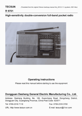
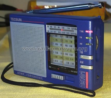
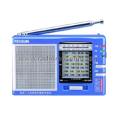
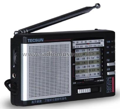
Dual Conversion Portable AM/FM/SW Radio Receiver R-9701
Tecsun 德生通用电器制造有限公司 Tecsun General Electric Manufacturing Co., Ltd; Dongguan (Guangdong, SC)
- Fabricant / Marque
- Tecsun 德生通用电器制造有限公司 Tecsun General Electric Manufacturing Co., Ltd; Dongguan (Guangdong, SC)
- Année
- 1998 ?
- Catégorie
- Bluetooth-Receiver and -Speaker
- Radiomuseum.org ID
- 333403


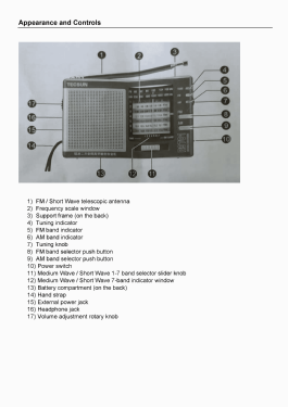


Picture from Tecsun public websites
Picture from Tecsun websites
Picture from Tecsun websites
Picture from Tecsun websites
Cliquez sur la vignette du schéma pour le demander en tant que document gratuit.
- No. de transistors
- Semi-conducteurs présents
- Semi-conducteurs
- Principe général
- Super hétérodyne, conversion double ou triple
- Gammes d'ondes
- PO, plus que 2 x OC et FM
- Tension / type courant
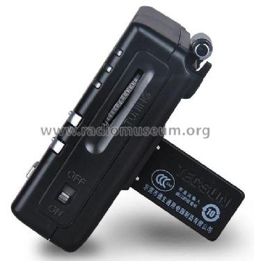
- Batteries / Alim. BT séparée avec fiche / AA: 2 x 1.5 / DC 3 Volt
- Haut-parleur
- HP dynamique à aimant permanent + bobine mobile / Ø 5.7 cm = 2.2 inch
- Matière
- Plastique moderne (pas de bakélite, ni de catalin)
- De Radiomuseum.org
- Modèle: Dual Conversion Portable AM/FM/SW Radio Receiver R-9701 - Tecsun 德生通用电器制造有限公...
- Forme
- Portable, appareil de poche. Taille < 20cm
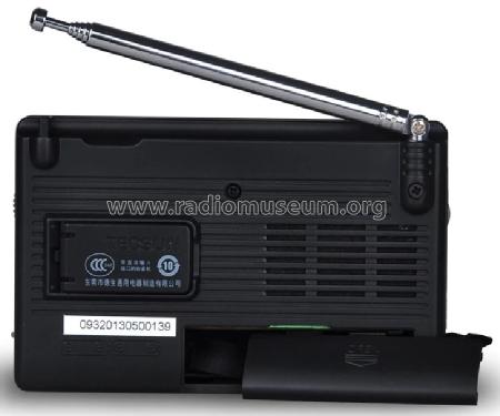
- Dimensions (LHP)
- 115 x 75 x 29 mm / 4.5 x 3 x 1.1 inch
- Remarques
-
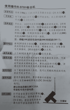
The Tecsun R-9701 is a small portable analog radio featuring FM, MW, and seven SW bands using dual conversion where the first discrete local oscillator uses seven crystals for improved stability, one per SW band.
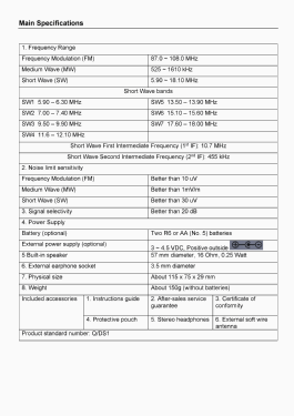
Main specifications
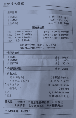
- Frequency coverage
- FM: 87.5 - 108 MHz (IF: 10.7 MHz)
- MW: 525 - 1610 kHz (IF: 455 kHz)
- SW: 5.90 - 18.10 MHz (1st IF: 10.7 MHz; 2nd IF: 455 kHz)
- SW1: 5.90 - 6.35 MHz
- SW2: 7.00 - 7.45 MHz
- SW3: 9.50 - 9.95 MHz
- SW4: 11.65 - 12.05 MHz
- SW5: 13.50 - 13.95 MHz
- SW6: 15.10 - 15.60 MHz
- SW7: 17.60 - 18.10 MHz
- Sensitivity
- FM: < 10 µV
- AM: < 1 mV/m
- SW: < 30 µV
- Selectivity: > 20 dB
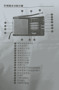
- Tuning LED indicator
- Band select LED indicators
- Electronic band selector
- 3.5 mm earphone socket (dual channel. mono)
- DC IN 3 V External power socket
- Cabinet colors: Grey, Blue
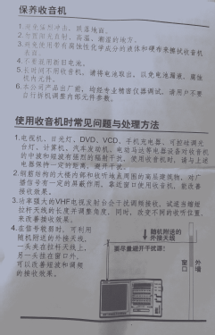
Included accessories
- Stereo earphones
- Carrying pouch
- External FM/SW soft antenna
- User manual
- Frequency coverage
- Poids net
- 0.168 kg / 0 lb 5.9 oz (0.37 lb)
- Auteur
- Modèle crée par Jose Mesquita. Voir les propositions de modification pour les contributeurs supplémentaires.
- D'autres Modèles
-
Vous pourrez trouver sous ce lien 36 modèles d'appareils, 35 avec des images et 22 avec des schémas.
Tous les appareils de Tecsun 德生通用电器制造有限公司 Tecsun General Electric Manufacturing Co., Ltd; Dongguan (Guangdong, SC)
Collections
Le modèle Dual Conversion Portable AM/FM/SW Radio Receiver fait partie des collections des membres suivants.
Contributions du forum pour ce modèle: Tecsun 德生通用电器...: Dual Conversion Portable AM/FM/SW Radio Receiver R-9701
Discussions: 1 | Publications: 1
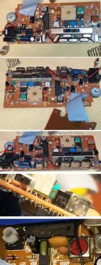
These observations are based on the "R-9701-V7" PCB with a date code of "2013.06.15" that also shows a "(2SK373)" label printed in the PCB silkscreen. This design version shows a few differences to a previous design as seen in the schematic diagram.
| R-9701-V7 2013.06.15 PCB | Original R-9701 schematic | |
| SW Front-End/1st Mixer | S9015 Bipolar (Q11) | K544 FET (Q11) |
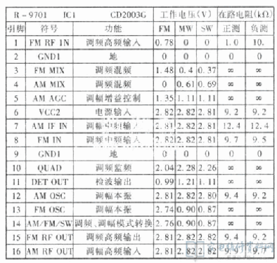
| AM/FM Tuner | CD2003GP DIP-16 (IC1) | CD2003GP DIP-16 (IC1) |
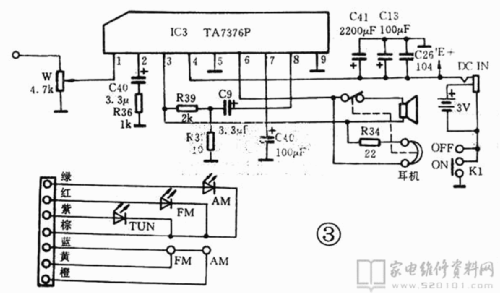
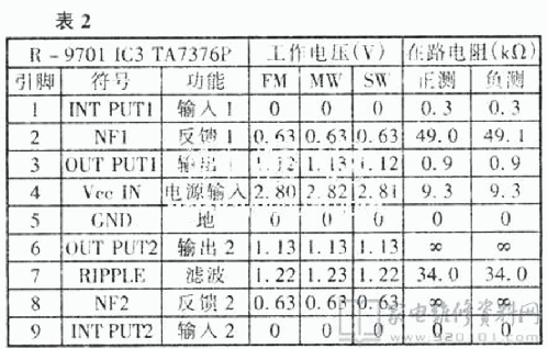
| Audio Amplifier | CD1622CB DIP-16 (IC2) | TA7376P SIP-9 (IC3) |
| Number of transistors | 10 (Q9 pads are empty) | 11 |
The antenna signal is passed thru a band pass filter (F3 in the schematic diagram, BPF88108 on the R-9701-V7 PCB).
The F3 secondary coil feeds the FM signal directly to the CD2003GP AM/FM Tuner IC RF FM input pin 1.
The F3 primary coil feeds the SW AM signals to the Front-End amplifier/1st Mixer Q11 thru a low pass filter C38, L3, C21.
The SW 1st local oscillator Q2 uses one from seven crystals (X1=16.8MHz; X2=17.9MHz; X3=20.4MHz; X4=22.5MHz; X5=24.4MHz; X6=26.05MHz; X7=28.5MHz), one per SW band.
The 1st IF output is handled by T9 and CF4 (10.7MHz) that passes the 1st IF signal to the CD2003GP IC AM RF input pin 16.
The band pass of each SW band is around 500 kHz, a common value in these kind of crystal stabilized local oscillators circuits (see the scale dial values).
The SW 2nd local oscillator is handled by the CD2003GP IC pin 12 using T7 and variable capacitor PVC4 section, where the 2nd IF signal at 455 kHz is obtained at pin 4 and injected to pin7 thru CF5 (455 kHz) amplified by Q9 (missing in the R-9701-V7 PCB).
The AM MW signal tuned by the magnetic antenna L1 and variable capacitor PVC1 section is passed directly to the CD2003GP IC AM RF input pin 16. The MW local oscillator is handled by the CD2003GP IC at pin 12 using T8 and variable capacitor PVC4 section. The MW IF frequency is 455 kHz.
The additional transistors are used as switches to select the different RF bands.
The audio signal from CD2003GP IC is passed to the Audio Amplifier IC thru capacitive coupling C12 and volume potentiometer.
The 16 Ohm 0.25 Watt 16T57Z-2 built-in speaker is driven in BTL mode by the Audio IC.
Jose Mesquita, 12.Nov.21