Oscilloscope System 7704A
Tektronix; Portland, OR
- Land
- USA
- Hersteller / Marke
- Tektronix; Portland, OR
- Jahr
- 1969
- Kategorie
- Service- oder Labor-Ausrüstung
- Radiomuseum.org ID
- 199764


Klicken Sie auf den Schaltplanausschnitt, um diesen kostenlos als Dokument anzufordern.
- Anzahl Röhren
- 1
- Röhren
- Anzahl Transistoren
- Halbleiter vorhanden.
- Halbleiter
- Wellenbereiche
- - ohne
- Betriebsart / Volt
- Wechselstromspeisung / 115; 230 Volt
- Lautsprecher
- - - Kein Ausgang für Schallwiedergabe.
- Material
- Metallausführung
- von Radiomuseum.org
- Modell: Oscilloscope System 7704A - Tektronix; Portland, OR
- Form
- Tischmodell, Zusatz nicht bekannt - allgemein.
- Abmessungen (BHT)
- 306 x 345 x 577 mm / 12 x 13.6 x 22.7 inch
- Bemerkung
-
DC to 200 MHz optimum pulse response
DC to 250 MHz bandwidth option
8 x 10cm display
Greather than 5cm/ns writing speed
Four-Plug-In flexibility
Vertical and horizontal mode switching
Versatile trigger source selection
CRT readout
Modular
CRT: 154-0644-00.Price in 1986 (Switzerland): 13313 CHF.
- Nettogewicht
- 13.6 kg / 29 lb 15.3 oz (29.956 lb)
- Originalpreis
- 2,400.00 $
- Datenherkunft
- -- Original-techn. papers.
- Literaturnachweis
- - - Manufacturers Literature (Swiss price list 1986)
- Autor
- Modellseite von Pius Steiner angelegt. Siehe bei "Änderungsvorschlag" für weitere Mitarbeit.
- Weitere Modelle
-
Hier finden Sie 388 Modelle, davon 376 mit Bildern und 92 mit Schaltbildern.
Alle gelisteten Radios usw. von Tektronix; Portland, OR
Sammlungen
Das Modell Oscilloscope System befindet sich in den Sammlungen folgender Mitglieder.
Forumsbeiträge zum Modell: Tektronix; Portland,: Oscilloscope System 7704A
Threads: 2 | Posts: 4
Die beiden Bilder
ID = 1141616
ID = 1113253
gehören definitiv nicht zum 7704A sondern zum 7704 Id= 250358
Gruss
Pius
Pius Steiner, 01.Aug.21
SERVICING THE 7704 HIGH-EFFICIENCY POWER SUPPLY
Source: Tektronix TekScope 1971
By Charles Phillips
Product Service Technician, Factory Service Center
This is the first in a series of articles on servicing the 7000-Series oscilloscopes. The 7704 serves as the basis for these articles since it contains most of the new circuitry, components and construction techniques we will be discussing. It is not our intent to discuss the general techniques used in troubleshooting oscilloscope circuitry as these were covered extensively in the February 1969 to February 1970 issues of TEKSCOPE. Copies of these articles are available through your field engineer.
Proper operation of the regulated low-voltage supplies is essential for the rest of the scope circuitry to function properly, so let's look at this section first.
The high-efficiency power supply used in the 7704 is a new concept in power supply design that results in appreciable savings in volume, weight and power consumption. It is called "high efficiency" because its efficiency is about 70% as compared to 45% for conventional supplies. The line-to-DC converter/ regulator contains most of the unconventional circuitry so our discussion will deal primarily with this portion.
First, let's briefly review the theory of operation. The high-efficiency power supply is essentially a DC-to-DC convener. The line voltage is rectified, filtered and used to power an inverter which runs at approximately 25 kHz. The frequency at which the inverter runs is determined basically by the resonant frequency of a series-LC network placed in series with the primary of the power transformer. The inverter drives the primary of the power transformer supplying the desired secondary voltages. These are then rectified, filtered and regulated for circuit use.
Pre-regulation of the voltage applied to the power transformer is accomplished by controlling the frequency at which the inverter runs. A sample of the secondary voltage is rectified and used to control the frequency of a monostable multivibrator. This multivibrator, in turn, controls the time that either half of the inverter can be triggered, thus controlling the inverter frequency. Circuit parameters are such that the multivibrator, and hence the inverter, always runs below the resonant frequency of the LC network. Remembering that the resonant LC network is in series with the primary of the power transformer, we can see that as the inverter frequency changes, the impedance of the LC network changes. The resultant change in voltage dropped across the LC network keeps the voltage applied to the primary constant. Pre-regulation to about 1% is achieved by this means.
Now, let's turn our attention to troubleshooting the supply. Assume you have made the usual preliminary checks; you have power to the instrument, the line selector on the rear of the instrument is in the correct position for the applied line voltage and the line voltage is within specified limits. The plug-ins have been removed to eliminate the possibility of their causing the power supply to malfunction.
With the instrument power off, check the two fuses located in the line selector cover on the rear of the instrument. If the line fuse, F800, is open the problem is probably in the line input circuitry. If the inverter fuse, F810, is open the inverter circuitry is probably faulty. In either case it will be necessary to remove the supply Irons the mainframe to snake further checks, This is easily done by removing the four screws on the rear panel that secure the power unit, then sliding the unit out the rear of the instrument.
Before removing the power-unit cover, check to see that the neon bulb on the left side of the power unit has stopped flashing. The primary storage capacitors C813 and C814 remain charged with high voltage DC for several minutes after the power line is disconnected.
 Simplified block diagram of high-efficiency low-voltage power supply.
When this voltage exceeds about 80 volts the neon bulb flashes. While servicing the power unit, the discharge time of the storage capacitors can be speeded up by temporarily disabling the inverter stop circuit. Pulling Q864 before turning off the scope power will allow the (sterner to keep running for a short time, thus draining most of the charge front the capacitors. A voltmeter reading between test points 810 and 811 on the line input board will indicate the charge remaining on the storage capacitors. Allow at least one minute for the current-limiting thermistors to cool before turning on the power again if you use this fast discharge technique.
Do not attempt to discharge the capacitors by shorting directly across them as this will damage them.
With the power-unit cover removed, orient the supply with the rectifier board on top, the line input board on the left and the inverter board on the right. This will make it convenient to get to all the test points as we go along.
LINE INPUT BOARD
First let's check the line input board. It's fairly easy to tell if this circuit is working. The neon bulb previously mentioned will start flashing when power is applied. On some units it assumes a steady glow, on others it continues to flash. The voltage reading on test points 810 and 811 should be approximately 300 volts DC depending upon the line voltage. Be careful not to ground any point in this circuit except test-point ground or chassis.
Typical troubles in this circuit causing the line fuse to open are shorted diodes on the bridge, CR810, or a shorted capacitor C8l0, C811, C813 or C814.
INVERTER BOARD
Next in line is the inverter circuit. The problems most common to this circuit are open fuse F810, shorted transistors Q825 or Q835 or shorted diodes CR825, CR835, CR828 or CR838. An open inverter fuse usually indicates trouble in the inverter.
Before working in this circuit, unplug the power cord and give the storage capacitors time to discharge. Remove the line selector cover containing the line and inverter fuses. We're now ready to make some resistance checks on the inverter board.
With your ohmmeter set to the x1 kΩ scale, take a reading between test points 826 and 836. The reading should be several megohms in one direction and ≈1.5 kΩ with the test leads reversed. Check between test points 836 and 820. You should get a high and low reacting as before. This checks the transistors and important diodes in the inverter stage. If you get a low reading in both directions on either of these tests, remove the transistor front the side having the low reading in both directions. A set of readings between the appropriate test points will show whether it is the diode or the transistor that is defective. Diodes CR826 and CR836 are not checked by the above procedure but will not prevent the inverter from running even if shorted. Once you achieve a high resistance on bout sides of the inverter, it will probably operate when you apply the proper power to it. However, before applying power, a quick check should be made on rectifier board test point 860 to ground. The resistance should be ≈ 2 kΩ to or 40 kΩ depending on the polarity of the meter leads.
You can now prepare to apply power to the instrument. Install the line selector cover. Remove Q860 to disable the pre-regulator circuit. Connect your test scope between test point 836 and ground on the inverter board. Vertical sensitivity should be. 50 V/div DC at the probe tip, the trace centered and the sweep speed set to 10 µs/div. Connect a voltmeter between the +75 V test point and ground on the rectifier board. Plug the scope into an autotransformer and with the line voltage set at zero volts, turn the instrument on. Slowly advance the line voltage while watching the test scope. If the trace moves up or down, the inverter still has problems. If the trace holds steady. the inverter should start as the line voltage approaches 80 volts. .A square wave of approximately 25 kHz and 200 volts will appear on the test scope. Do not advance the line voltage any further. The +75 volt supply should not be allowed to exceed 75 volts to prevent blowing the inverter fuse.
RECTIFIER BOARD
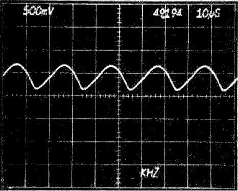
You are now ready to check the pre-regulator circuitry. Turn off the scope and return the line voltage to zero volts. Replace Q860 in its socket. Slowly advance the line voltage while monitoring the +75 volt supply. If the +75 volts holds steady, you can advance the line voltage to a normal setting. If the voltage is not stable or if the signal being monitored on test point 836 on the inverter board is erratic in frequency, the pre-regulator is not working properly. The quickest method of troubleshooting this circuit is to check the associated transistors with a curve tracer or ohmmeter. The waveforms shown on the facing page are typical for a properly operating supply.
MECHANICAL CONSIDERATIONS
Most of the components in the power supply are readily accessible from the top of the printed circuit boards. However, when it is necessary to remove a soldered-in component, we suggest you remove the circuit board from the assembly and unsolder the component front the back side of the board. The line input board and the rectifier board are readily removed by loosening two or three screws. The inverter board is somewhat more difficult to remove; the manual gives the proper procedure.

Low-voltage supply removed for easy servicing. Line input board is on the left side, rectifier board on top, and just the edge of the inverter board is visible at the right.
Care should be exercised when replacing Q825 or Q835 located on the ceramic heat sink on the inverter board. The mounting studs are soldered into the printed circuit board and may be broken loose by applying excessive torque.
When placing the power unit back into the mainframe take care to properly dress the power unit cables between the power unit and the logic board. Lowering the swing-down gate on the right side of the instrument will let you guide the cables into place.
In the next issue of TEKSCOPE we will discuss the 7704 high voltage power supply.

Typical waveform at TP836 for properly operating supply. Mid-screen is 0 Volts.

Waveform at TP860. Note frequency is twice that at TP836.
Waveform at TP859. Frequency increased slightly due to line voltage
Pius Steiner, 24.Sep.12