Spectrum Analyzer 7L13
Tektronix; Portland, OR
- Country
- United States of America (USA)
- Manufacturer / Brand
- Tektronix; Portland, OR
- Year
- 1974
- Category
- Service- or Lab Equipment
- Radiomuseum.org ID
- 257048
- Number of Transistors
- Semiconductors present.
- Semiconductors
- Main principle
- Superhet, double/triple conversion
- Wave bands
- Wave Bands given in the notes.
- Power type and voltage
- Powered by external power supply or a main unit.
- Loudspeaker
- - - No sound reproduction output.
- Material
- Metal case
- from Radiomuseum.org
- Model: Spectrum Analyzer 7L13 - Tektronix; Portland, OR
- Shape
- Chassis only or for «building in»
- Dimensions (WHD)
- 208 x 127 x 340 mm / 8.2 x 5 x 13.4 inch
- Notes
-
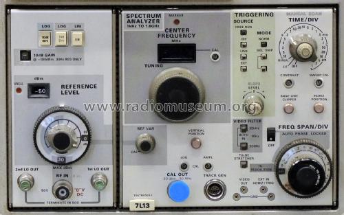
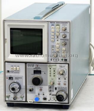
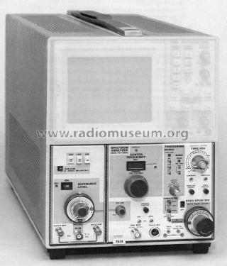
The Tektronix 7L13 Spectrum Analyzer is a triple-width plug-in high-performance communication spectrum analyzer that plugs into and operates with the 7000-series mainframe oscilloscopes. It is a swept front end analyzer that displays absolute amplitude information of signals within the frequency span of 0 Hz to 1.8 GHz. Time domain characteristics, within a 3 MHz bandpass, can also be displayed.
ELECTRICAL CHARACTERISTICS
Frequency Operating Range
1 kHz to 1.8 GHz continuously variable; accuracy ± (5 MHz + 20% of the Freq Span/Div).Frequency Span
Calibrated 200 Hz/div to 100 MHz/div in 1-2-5 sequence, plus 0 Hz and MAX SPAN positions. In the 0 Hz position, the analyzer is a fixed tuned receiver for time domain analysis. In the MAX SPAN position the frequency span is approximately 1.8 GHz. Accuracy: Within 5% of the indicated frequency separation. Linearity over the center 8 divisions is within 5%.Calibrator
50 MHz ±0.01% -30 dBm ±0.3 dB. Harmonics of 50 MHz are generated for frequency span calibration.Reference Level
Selectable -100 dBm to +30 dBm in 10 dBm steps. Continuously variable between steps.Log Display Mode Dynamic Range
70 dB at 10 dB/div, accuracy 1 dB/10 dB to a maximum of ±1.5 dB over 70 dB range and 14 dB at 2 dB/div, accuracy 0.4 dB/2 dB for a maximum of 1.0 dB over the 14 dB range.RF Attenuation
0 dB to 60 dB in 10 dB steps ± (0.2 dB or 1% of dB reading, whichever is greater).Resolution Bandwidth (6 dB down)
30 Hz to 3 MHz in decade steps ±20%; shape facto (60:6 dB ratio): 12:1 or better for 30 Hz resolution and 4:1 or better with resolution of 300 Hz or more except 3 MHz. Max. bandwidth 60 dB down with 3 MHz resolution, is 13 MHz.Video Filtering
Three selections of video filtering; 10 Hz, 300 Hz and 30 kHz are provided for signal or noise averaging.CW Sensitivity
-128 dBm at 30 Hz Resolution; -120 dBm at 300 Hz resolution; -110 dBm at 3 kHz Resolution; -100 dBm at 30 kHz Resolution; -90 dBm at 300 kHz Resolution; -80 dBm at 3 MHz Resolution.Internal Spurious Responses
Less than -100 dBm, referred to the 1st mixer input.Intermodulation Distortion
100 kHz - 1.8 GHz: Third order: 70 dB down from two -30 dBm signals. Second order: 70 dB down from two -40 dBm signals (within any frequency span).
100 kHz - 1 kHz: Intermodulation products (3rd and 2nd) are down 50 dB or more for the same input level as above.Incidental FM
Phase locked mode: 10 Hz (P-P) maximum; not phase locked: 10 kHz (P-P) maximum.Display Flatness
+1 dB, -2 dB over any selected span with respect to level at 50 MHz.Maximum Input Power Level
-30 dBm with the RF Attenuator at 0 dB, for linear operation, +30 dBm with the RF Attenuator at 60 dB. (+30 dBm is also the power rating of the RF Attenuator).
Note: The maximum input power level to the RF Attenuator is 1 watt average and 200 watts peak. +13 dBm will destroy the 1st mixer.Sweep Modes and Rate
Selection of an external sweep source, manual sweep, or calibrated sweep rates from 10 s/Div to 1 µs/Div in a 1-2-5 sequence are provided. Sweep rate accuracy is within 5% of that selected.Triggering Modes
INTernal, EXTernal selects the signal applied to the EXT IN HORIZ/TRIG connector and LINE selects a sample of the mainframe line voltage.
- Mentioned in
- - - Manufacturers Literature (Tektronix Instruction Manual, 1974 products catalog p.167)
- Author
- Model page created by Bernhard Nagel. See "Data change" for further contributors.
- Other Models
-
Here you find 388 models, 376 with images and 92 with schematics for wireless sets etc. In French: TSF for Télégraphie sans fil.
All listed radios etc. from Tektronix; Portland, OR