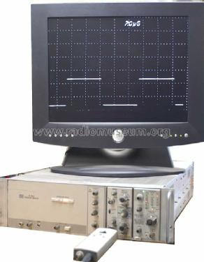
Transient Digitizer R7912
Tektronix; Portland, OR
- Country
- United States of America (USA)
- Manufacturer / Brand
- Tektronix; Portland, OR
- Year
- 1973
- Category
- Service- or Lab Equipment
- Radiomuseum.org ID
- 181143

- Number of Tubes
- 1
- Valves / Tubes
- 154-0698-00
- Number of Transistors
- Semiconductors present.
- Semiconductors
- Main principle
- none
- Wave bands
- - without
- Power type and voltage
- 90/132; 180/264 Volt
- Loudspeaker
- - - No sound reproduction output.
- Material
- Metal case
- from Radiomuseum.org
- Model: Transient Digitizer R7912 - Tektronix; Portland, OR
- Shape
- Rack
- Dimensions (WHD)
- 482 x 130 x 720 mm / 19 x 5.1 x 28.3 inch
- Notes
- The R7912 Transient Digitizer is a high-speed signal acquisition instrument capable of operating in either an analog or a digital mode. Acquired waveforms up to 500MHz (1GHz direct access) are converted to a speed format more suitable for viewing on a standard video monitor. Optionally, the R7912 can convert the acquired waveform to digital form and store the information in a local semiconductor memory (option 14). In this Digital mode, the R7912 operates as an analog-to- digital converter with an effective clock rate of about 100 GHz.
- Net weight (2.2 lb = 1 kg)
- 18.3 kg / 40 lb 4.9 oz (40.308 lb)
- Source of data
- - - Data from my own collection
- Mentioned in
- - - Manufacturers Literature (TekScope Vol. 5 No. 6, Nov-Dec 1973)
- Author
- Model page created by Pius Steiner. See "Data change" for further contributors.
- Other Models
-
Here you find 386 models, 374 with images and 92 with schematics for wireless sets etc. In French: TSF for Télégraphie sans fil.
All listed radios etc. from Tektronix; Portland, OR
Collections
The model Transient Digitizer is part of the collections of the following members.
Forum contributions about this model: Tektronix; Portland,: Transient Digitizer R7912
Threads: 1 | Posts: 2
Source: Tektronix R7912 Transient Digitizer Service Manual
THEORY OF OPERATION
Introduction
The R7912 Transient Digitizer allows extremely short rise-time signals to be acquired, converted to digital format, and stored in a local memory. Its operation appears at first to be like that of an oscilloscope, but the similarity is slight. Like an oscilloscope, the R7912 accepts a variety of input signals through conventional 7000-Series plug-in amplifiers. The signal is used to vertically deflect an electron beam as it is swept horizontally under control of the time base plug-in. The similarity ends there.
The Scan Converter
Instead of the usual phosphor-coated CRT found in an oscilloscope, the R7912 uses a specially designed tube called a Scan Converter (see Fig. 3-1). The Scan Converter tube has a small silicon diode target at its center. The electron beam, deflected by the time base plug-in and the amplified input signal (called the writing beam), is swept across this target.

Fig. 3-1. The R7912 Scan Converter tube.
The Target
Composed of an array of silicon diodes on a single chip 1.3 cm by 0.95 cm, the target has a diode density of about 800 diodes per linear centimeter (see Fig. 3-2).
This target diodes are formed by diffusing a p-type material into an n-type substrate. The side of the target containing these diffusions faces a reading gun that continuously scans the diode array with an electron beam. This electron beam is referred to as the reading beam, and it deposits a charge on the target surface. The deposited charge causes the target diodes to reverse bias and charge toward the cathode potential of the reading gun. In the charged condition, the target diodes are in an unwritten state.

Fig. 3-2. Scan Converter diode target.
Writing a Trace on the Target
The writing beam, carrying the information from the plug-ins, traces an image of the waveform on the back side of the target. Bombardment of the target by the intense writing beam creates electron-hole pairs near the substrate surface. The holes diffuse across the substrate to those diodes opposite the writing beam, causing them to lose their charge. This discharged condition is the written state.
Reading the Target
The reading beam reads the waveform image by recharging the written diodes while it scans the target. Each time the reading beam recharges an area of written diodes, a signal current is generated in the target lead. The operational mode of the R7912 determines what this signal current is used for.
TV Mode
When the R7912 is in the TV mode (NON-STORE), the reading beam scans the target in a horizontal format similar to that used in conventional television systems. The target lead signals obtained while reading in this mode are used to generate video output compatible with television monitors such as the Tektronix 632 Picture Monitor. The TV monitor provides an immediate display of the written trace, and is of great value during initial "setup."
Digital Mode
The Digital mode is of primary importance when operating the R7912 with a computer. In this mode, waveforms are converted to digital information, stored in a self-contained memory, and made available to the computer.
In the Digital mode, the reading beam scans the target vertically. Each vertical scan consists of 512 discrete steps down the target. After each vertical scan is complete, the reading beam retraces to the top of the target and advances one step horizontally. There are 512 horizontal steps across the target (see Fig. 3-3). This scanning technique produces a 512 X 512 matrix of addressable areas on the target.

Fig. 3-3. Target scanning in Digital mode.
After each vertical scan is complete, and during the time the reading beam retraces to the top of the target, a binary word is issued by the horizontal address counter. This binary word indicates the horizontal position of the next vertical column to be scanned by the reading beam.
Digitizing the Trace
As the reading beam steps down each vertical column, it pauses at each step for about 100 nanoseconds. The circuitry determines whether or not the diode area under the beam has been written. If the area is unwritten (no target lead signal), the beam steps down to the next addressable area on the target. The step from one unwritten area to the next also takes about 100 nanoseconds.
When the reading beam steps into a written area of the target, the beam recharges the written diodes, producing a target lead signal. The signal causes the reading beam to pause for 1.6 microseconds while a binary word describing its vertical position on the target is issued. The delay allows the vertical word to be stored in the R7912 memory.
Since the writing beam is of finite diameter (approximately 0.02 millimeter), it covers more than one target diode at any given time. Indeed, the target diode density is such that the beam covers several diodes wholly, and several more partially. Writing beam intensity, as controlled by the front-panel INTENSITY control, also affects the number of diodes discharged.
The finite beam diameter results in a trace that may be several vertical addresses wide. As the reading beam steps downward across the discharged trace image, the lead signal maintained.
To prevent vertical addresses from being issued at every vertical position throughout the beam thickness, only the rising and falling edges of the target lead signal are detected. A diagram of the reading process is given in Fig. 3-4. Note that the data is issued in the following sequence: horizontal word - vertical word - vertical word; next horizontal word - vertical word - vertical word, etc.
Storing the Data
A sweep trigger begins the memory loading process in the R7912. In Single-Sweep mode, the trigger by itself is sufficient, but in Repetitive-Sweep mode, the trigger must be preceded by a Load Memory command. Figure 3-5 describes a memory load cycle for both sweep modes.
Since the reading beam operates continuously, the point on the target where storing begins is dependent upon sweep speed, waveform repetition rate, and Load Command timing. As a result, the first horizontal address stored may be any of the 512 addresses on the target. The vertical words associated with that horizontal are stored next, followed by the next horizontal word. Reading and storing continues until the first column read is reached again. After all waveform data are stored, the R7912 requests interrupt. Address strap options in each R7912 indicate to the controller which instrument has data, and a service routine can be initiated.

Fig. 3-4. Reading the diode target

Fig. 3-5. Normal operating sequence
Vielen Dank an Herrn Dietmar Rudolph, der meine Bilder nachbearbeitet hat.
Pius Steiner, 26.Aug.10