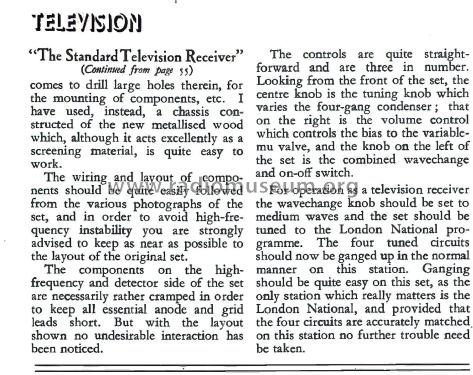
The Standard Television Receiver
Television, Television & Short-Wave World, Electronics & Television and Short Wave World & Electronic Engineering,
- Produttore / Marca
- Television, Television & Short-Wave World, Electronics & Television and Short Wave World & Electronic Engineering,
- Anno
- 1934
- Categoria
- Kit, scatola di montaggio (parti sfuse e istruzioni o solo istruzioni di montaggio)
- Radiomuseum.org ID
- 361664
Clicca sulla miniatura dello schema per richiederlo come documento gratuito.
- Numero di tubi
- 6
- Principio generale
- A circuiti accordati (amplif. diretta) senza reazione; A valvole con griglia schermo (solo se 1926-1935)
- Gamme d'onda
- Onde medie (OM) e onde lunghe (OL).
- Tensioni di funzionamento
- Alimentazione a corrente alternata (CA) / 200; 230; 250 Volt
- Altoparlante
- - - Nessuna uscita audio.
- Materiali
- Vari materiali
- Radiomuseum.org
- Modello: The Standard Television Receiver - Television, Television & Short
- Forma
- Chassis o in scatola da montaggio
- Annotazioni
-
The Standard Television Receiver
Designed and described by S. Rutherford Wilkins in Television, February 1934.
This early television receiver was engineered for simplicity, affordability, and high performance. It was specifically intended for use with mechanical television display systems, such as the mirror drum visor, and aimed to deliver enough power and frequency response to ensure clear, well-defined images.
Its primary functions included:
- Receive Frequency: Broadcast & longwave but tuned to 1.2 MHz (250 metres), specifically for the London National television transmissions of the early 1930s.
- Wide Frequency Response: The receiver was engineered to handle modulation frequencies up to 10,000 cycles per second (10 kHz), ensuring adequate picture definition without significant attenuation of high-frequency signals.
- Bandpass Selectivity: Selectivity was achieved using a bandpass filter system with iron-cored coils, arranged to provide a wide enough bandwidth for video signals while minimizing interference from nearby radio transmitters. Two filters in cascade enhanced selectivity and frequency response.
- Amplification Stages: The receiver typically used a single screen-grid amplification stage, sufficient for strong local signals. For weaker signals, additional amplification stages could be added.
- Detection and Audio Amplification: Diode detection was employed for linear rectification of the video signal, using a double-diode-triode valve. The detected signal was then amplified by the triode section and further processed by high-efficiency output pentodes (e.g., Mazda A.C.2 Pens) connected in parallel to provide up to 4 watts of output.
- Output and Modulation: The amplified signal was strong enough to modulate a Kerr cell in a mirror-drum apparatus, with output voltage and power tailored for this purpose. A bias voltage (around 400 volts) for the Kerr cell was derived from the receiver’s high-tension supply.
- Synchronisation: The receiver extracted synchronisation signals from the same input as the video modulation, ensuring proper timing of the mechanical display.
- Circuit Stability: Careful use of resistance-capacity coupling, decoupling resistors, and screening minimised distortion, oscillation, and unwanted interactions between circuit stages.
Summary:
This early TV receiver combined selective bandpass filtering, sensitive amplification, and robust output stages to deliver video signals for mechanical television systems. Its design balanced simplicity, cost, and performance, laying the groundwork for more advanced electronic television receivers in later years.
- Bibliografia
- -- Original prospect or advert (Television Feb 1934, Pages 33-35 & 86)
- Autore
- Modello inviato da Gary Cowans. Utilizzare "Proponi modifica" per inviare ulteriori dati.
- Altri modelli
-
In questo link sono elencati 1 modelli, di cui 1 con immagini e 1 con schemi.
Elenco delle radio e altri apparecchi della Television, Television & Short-Wave World, Electronics & Television and Short Wave World & Electronic Engineering,


