- Land
- Grossbritannien (UK)
- Hersteller / Marke
- Westinghouse Brake and Saxby Signal Co., Ltd. & Westinghouse Brake & Signal Co.; London
- Jahr
- 1944 ?
- Kategorie
- Strom-Versorgung oder Spannungsstabilisator
- Radiomuseum.org ID
- 361337
The Engineer Jan 11, 1946, Pages 36,37

Wireless World Sep 1945, Page Ad 8.
- Hauptprinzip
- Spezialschaltung (siehe Bemerkungen)
- Wellenbereiche
- - ohne
- Betriebsart / Volt
- Wechselstromspeisung / 50 Hz, 190-260 Volt
- Lautsprecher
- - - Kein Ausgang für Schallwiedergabe.
- Material
- Metallausführung
- von Radiomuseum.org
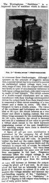
- Modell: Stabilistor - Westinghouse Brake and Saxby
- Form
- Schweres Gerät für Militär oder Industrie (Boatanchor > 20 kg).
- Bemerkung
-
The Westinghouse Stabilistor was an advanced AC voltage stabiliser designed to deliver a stable, undistorted output voltage for single-phase 50 Hz applications, even under wide variations in input voltage (190–260 V) and load (no load to full load). Its design leverages magnetic saturation and a specialised filtering circuit to achieve high performance and reliability.
Key Functional Components
- Double-Wound Transformer:
The double-wound transformer is central to the Stabilistor’s operation. It is designed to operate near magnetic saturation, allowing it to self-regulate the output voltage in response to input supply or load fluctuations. Working in conjunction with an autotransformer and interconnected windings forms a feedback mechanism that dynamically adjusts the core’s magnetic flux. This enables rapid compensation for voltage or load changes, maintaining output stability and minimising waveform distortion. The double-wound construction also helps suppress third-harmonic currents, especially when paired with the resonant filter circuit, ensuring the output remains sinusoidal and undistorted. - Autotransformer:
Interconnected with the double-wound transformer, the autotransformer assists in voltage regulation and further enhances the system’s ability to respond quickly to load and supply variations. - Filter Circuit (Capacitor and Choke in Series):
This filter is connected across the output and serves two purposes:- At 50 Hz, it acts as a capacitive load, drawing a leading current necessary for the stabilising action.
- At 150 Hz (the third harmonic), it becomes resonant, providing a low-impedance path that effectively short-circuits third-harmonic magnetising currents, thus maintaining a pure sine wave output.
Performance and Operational Characteristics
- Voltage Stabilization:
Guarantees output within ±2% for all loads and input voltages between 190 V and 260 V. Tighter regulation is possible if either the input or the load is held constant5. - Waveform Quality:
The output waveform remains virtually undistorted across the full load range, thanks to the harmonic suppression provided by the transformer/filter combination. - Response Time:
The system responds almost instantaneously to changes in load or input voltage, making it suitable for sensitive equipment. - Efficiency:
The Stabilistor achieves an efficiency of approximately 85%. - Power Factor:
The input power factor is about 0.7 lagging at full output when supplying a unity power factor load. Loads with inherently low power factor should be corrected to maximise voltage stability and load capacity. - Frequency Sensitivity:
Output voltage changes by about ±0.6% for every ±0.2 Hz deviation from the nominal 50 Hz supply frequency.
- Double-Wound Transformer:
- Literaturnachweis
- Wireless World (The), London (WW, 79) (Nov 1944, Pages 349 -341.)
- Literatur/Schema (1)
- -- Original prospect or advert (The Engineer Jan 11, 1946, Pages 36,37.)
- Autor
- Modellseite von Gary Cowans angelegt. Siehe bei "Änderungsvorschlag" für weitere Mitarbeit.
- Weitere Modelle
-
Hier finden Sie 2 Modelle, davon 2 mit Bildern und 0 mit Schaltbildern.
Alle gelisteten Radios usw. von Westinghouse Brake and Saxby Signal Co., Ltd. & Westinghouse Brake & Signal Co.; London