Standard All Wave Receiver
Wireless Weekly Magazine, Sydney
- Country
- Australia
- Manufacturer / Brand
- Wireless Weekly Magazine, Sydney
- Year
- 1933
- Category
- Kit (Parts plus instruction) or building instructions only
- Radiomuseum.org ID
- 331998


Click on the schematic thumbnail to request the schematic as a free document.
- Number of Tubes
- 11
- Valves / Tubes
- Main principle
- Superhet with RF-stage; ZF/IF 585 & 186 kHz; 2 AF stage(s)
- Tuned circuits
- 14 AM circuit(s)
- Wave bands
- Broadcast plus more than 2 Short Wave bands.
- Power type and voltage
- Alternating Current supply (AC) / 200-260 Volt
- Loudspeaker
- Electro Magnetic Dynamic LS (moving-coil with field excitation coil)
- Material
- Metal case, TUBES VISIBLE
- from Radiomuseum.org
- Model: Standard All Wave Receiver - Wireless Weekly Magazine,
- Shape
- Chassis only or for «building in»
- Notes
-
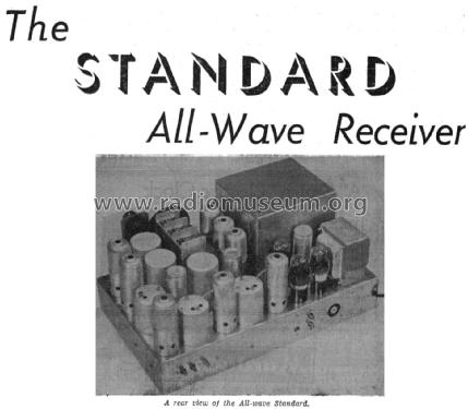
Standard All Wave Receiver
11 valve superhet receiver based on the Wireless Weekly 1933 Standard Superhet with the addition of 3 extra valves for a shortwave superhet preselector.
The shortwave section uses the Lekmek All-Wave unit SW10/200.
See also the Lekmek 1101.From the Wireless Weekly December 15, 1933, Page 52.
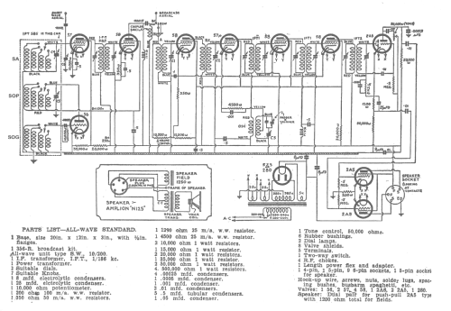
Doubtless many of the vast number of people who have built up the Standard Superhet will be interested in “all-wave” reception now that this particular form of broadcasting is attracting so much attention. Here is the description of the set which can be made up to use every component of the original Standard superhet except the base. On the broadcast band the performance of the Standard is retained exactly, and for short-wave reception three extra valves are fitted, resulting in tremendous gain. The overall amplification of the receiver is so great that even the weakest of overseas stations can be played with the volume control set less than half-way open. The construction of the set is not difficult, as the “all-wave” coil assembly is supplied complete in a unit with coloured leads.
AMPLIFICATION
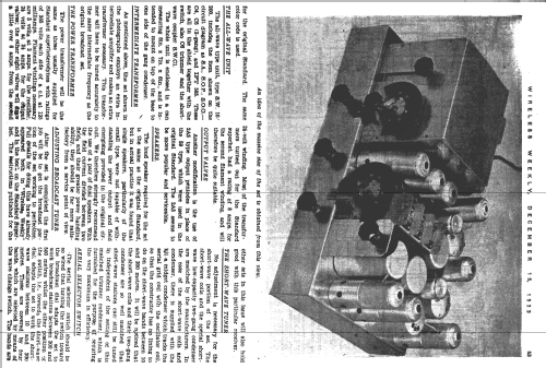
On the short waves the amplification is carried out at several frequencies, but no attempt is made to amplify the signals at their original high frequency. It has been repeatedly proved that it is not possible to do so efficiently. The incoming signal is mixed in the first detector with the oscillator’s output to make a signal at a frequency of 585 kc/s. There is an intermediate amplifier at this frequency in the shortwave end of the set and a second intermediate amplifier at the same frequency is provided by setting the dial of the broadcast tuner at this frequency. Actually, of course, this amplifier is the RF amplifier of the broadcast receiver. The frequency of the signal is again changed in the autodyne of the broadcast portion of the set to 186 kc/s and further amplification takes place at this frequency. If desired, the one 186 kc/s intermediate stage of the original Standard can be used, although in the actual set shown in the photographs in this article it will be noticed that a second intermediate amplifier at 186 kc/s has been added. From all this, it will be seen that tremendous amplification of the signal is provided, and, since it occurs at different frequencies, there is not much tendency towards instability.
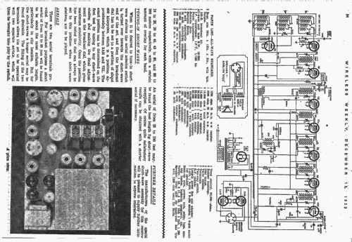
EASE OF CONTROL
For tuning in the shortwave stations, a separate dial connected to a separate gang condenser of low capacity is provided, so that the adjustment of the dial when tuning in short-wave stations is little more critical than on the broadcast bands.
- Mentioned in
- Wireless Weekly (Australia) (December 15, 1933, Page 52)
- Author
- Model page created by Gary Cowans. See "Data change" for further contributors.
- Other Models
-
Here you find 19 models, 13 with images and 19 with schematics for wireless sets etc. In French: TSF for Télégraphie sans fil.
All listed radios etc. from Wireless Weekly Magazine, Sydney