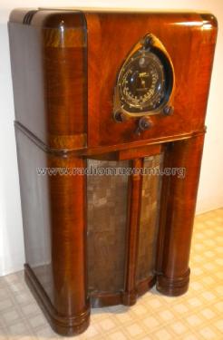
12-S-265 Ch=1204
Zenith Radio Corp.; Chicago, IL
- Country
- United States of America (USA)
- Manufacturer / Brand
- Zenith Radio Corp.; Chicago, IL
- Year
- 1937/1938
- Category
- Broadcast Receiver - or past WW2 Tuner
- Radiomuseum.org ID
- 67326
-
- alternative name: Chicago Radio Lab
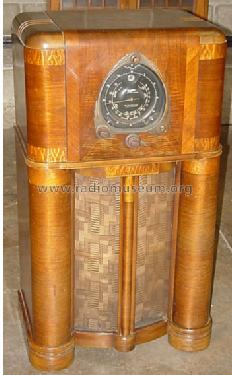
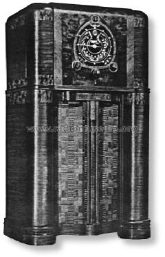
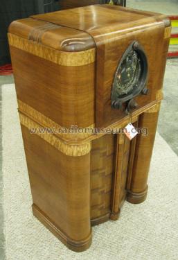
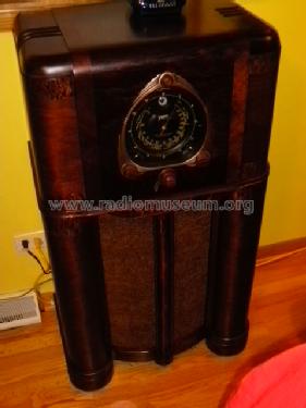
Zenith Model 12-S-265 (1937) Copy from Ebay

Copy gen. von John Goller Radio Attic

eBay.com 130655475943 seller: bm071

eBay.com 130655475943 seller: bm071

By courtesy of William Kendrick, USA


eBay seller: tnorthup (USA). #6612636068
eBay seller: tnorthup (USA). #6612636068
eBay seller: tnorthup (USA). #6612636068
eBay seller: tnorthup (USA). #6612636068

eBay.com 130655475943 seller: bm071

Ebay USer danteboy518 Item 320882243409
Ebay USer danteboy518 Item 320882243409
Ebay USer danteboy518 Item 320882243409
Ebay USer danteboy518 Item 320882243409
Ebay USer danteboy518 Item 320882243409
Ebay USer danteboy518 Item 320882243409
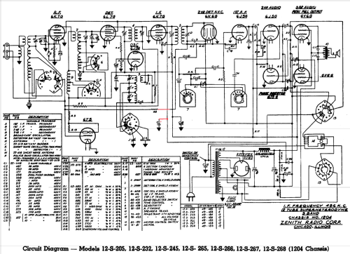
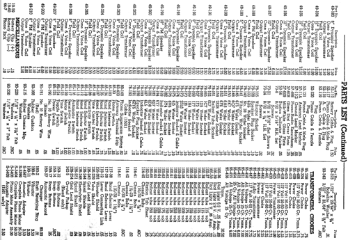
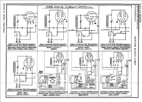
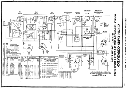
Click on the schematic thumbnail to request the schematic as a free document.
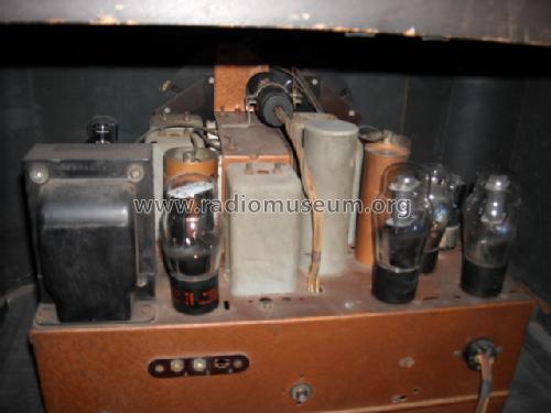
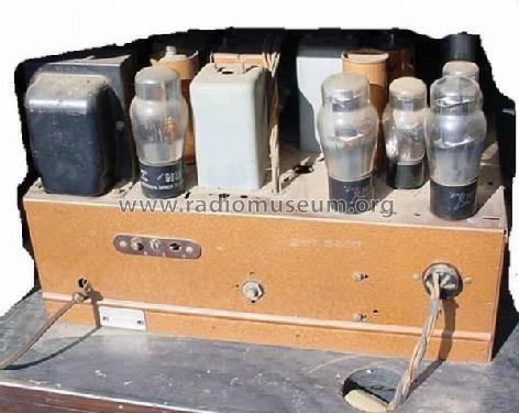
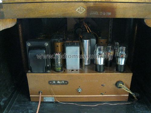
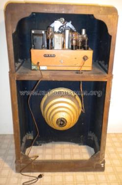
- Number of Tubes
- 12
- Main principle
- Superhet with RF-stage; ZF/IF 456 kHz
- Tuned circuits
- 7 AM circuit(s)
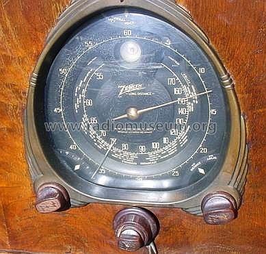
- Wave bands
- Broadcast, Short Wave(s) and Police.
- Power type and voltage
- Alternating Current supply (AC) / 115 Volt
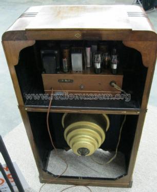
- Loudspeaker
- Electro Magnetic Dynamic LS (moving-coil with field excitation coil) / Ø 12 inch = 30.5 cm
- Power out
- 15 W (unknown quality)
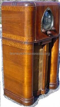
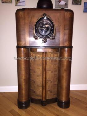
- Material
- Wooden case
- from Radiomuseum.org
- Model: 12-S-265 Ch=1204 - Zenith Radio Corp.; Chicago,
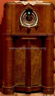
- Shape
- Console with any shape - in general
- Dimensions (WHD)
- 25 x 43 x 15 inch / 635 x 1092 x 381 mm
- Notes
- The schematic diagram got corrections (red). These lines are already missing in the Zenith drawing as well as in Riders and in Beitman.
Bunis predates by one year. This may be based on Zenith 1937 advertising "Preview of new products" in "Blast of the Past". And usually the season started mostly the previous year to get the X-mas sales.
- Price in first year of sale
- 140.00 $
- External source of data
- Ernst Erb
- Source of data
- The Radio Collector's Directory and Price Guide 1921 - 1965
- Circuit diagram reference
- Rider's Perpetual, Volume 8 = 1937 and before
- Mentioned in
- Collector's Guide to Antique Radios 4. Edition
- Literature/Schematics (1)
- Zenith Radio The Glory Years 1936-1945
- Literature/Schematics (2)
- Pre-War Consoles
- Other Models
-
Here you find 4491 models, 4096 with images and 3595 with schematics for wireless sets etc. In French: TSF for Télégraphie sans fil.
All listed radios etc. from Zenith Radio Corp.; Chicago, IL
Collections
The model 12-S-265 is part of the collections of the following members.
Forum contributions about this model: Zenith Radio Corp.;: 12-S-265 Ch=1204
Threads: 3 | Posts: 3
Correction made (red). These lines are already missing in the Zenith drawing as well as in Riders and in Beitman. Schematic with the erroneous correction is deleted.
Konrad Birkner † 12.08.2014, 22.Aug.10
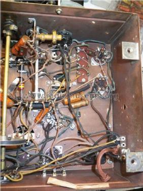
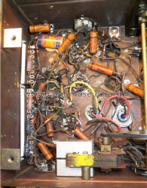
I am currently restoring a Zenith 12S265. In the center of the schematic that the radio museum lists shows a capacitor called "C". The schematic shows this capacitor being connected to R8. I believe this to be in error. The 12S265 radio I have has this capacitor connected to the first line directly to the right. The line to the right connects to the screen grids of the I.F. amplifier (pin 4 of the 6K7G) The 1st detector (pin 4 of the 6L7G) and to the R.F amplifier (pin 4 of the 6K7G). The line also connects to the positive side of capacitor C25 which connects to the junction of the two 11 Kohm candohm wire wound resistors. This capacitor called "C" on the prints should be called C7 which in my radio and shown on the schematic is a .1 microfarad 400 V.D.C part # 22-170 paper tubular capacitor. Also R8 should be connected to R2 found at the bottom of the secondary winding I. F. transformer #5 and connected to C9. I believe coming off of this R2 resistor is the A.V.C. voltage which goes out to the R.F. amplifier 1st detector, the tuning eye tune, (6T5) and the 6K7 I.F. amplifier.
Hope this will be helpfull to someone!
John
John Bartholomew, 22.Aug.10
In restoreing this particular radio I found that the two tuning drive belts had to be replaced. After doing much searching I found rubber O-rings from Mercury Marine that worked perfectly. The part number for the large one is 25-70937,[ I.D. is 3 1/2 inch---width is .135 inch ]. The part number for the small one is 25-20863,[ I.D. is 2.625 inch.--- width is .135 inch ]. The website for Mercury Marine is, www.mercurymarine.com.
Ross Hoff, 22.Sep.09