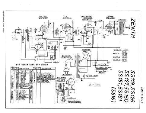
5S119 Ch=5516
Zenith Radio Corp.; Chicago, IL
- Produttore / Marca
- Zenith Radio Corp.; Chicago, IL
- Anno
- 1937
- Categoria
- Radio (o sintonizzatore del dopoguerra WW2)
- Radiomuseum.org ID
- 19043
-
- alternative name: Chicago Radio Lab


Thanks to ebayer larry21751
With courtesy by Ebayseller larry21751
With courtesy by Ebayseller larry21751
With courtesy by Ebayseller larry21751
With courtesy by Ebayseller larry21751

Thanks to ebayer larry21751
Thanks to ebayer larry21751

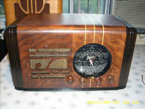
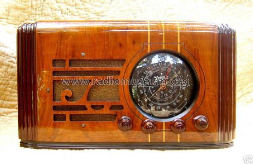
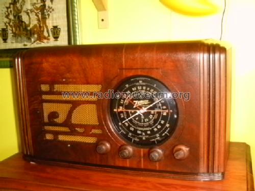
this is my zenith table radio model 5-S-119
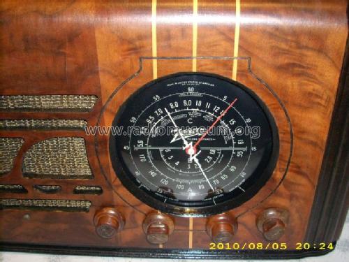
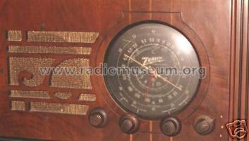
close up of the dial

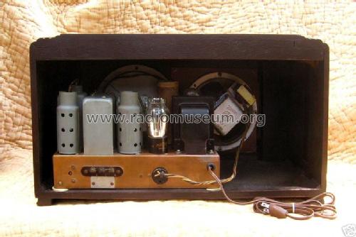
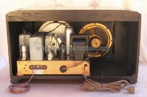
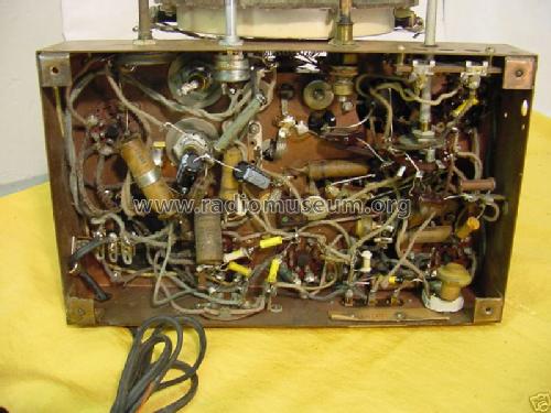
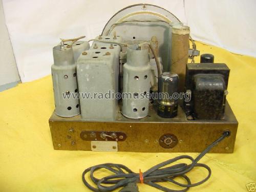
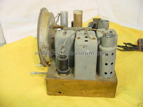
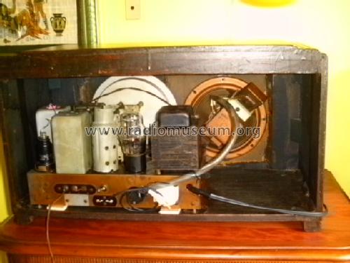
back of the set

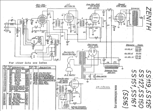
Clicca sulla miniatura dello schema per richiederlo come documento gratuito.
- Numero di tubi
- 5
- Principio generale
- Supereterodina (in generale); ZF/IF 456 kHz
- Gamme d'onda
- Onde medie (OM), corte (OC) e tropicali/polizia.
- Tensioni di funzionamento
- Alimentazione a corrente alternata (CA) / 115 Volt
- Altoparlante
- AP elettrodinamico (bobina mobile e bobina di eccitazione/di campo) / Ø 6 inch = 15.2 cm
- Materiali
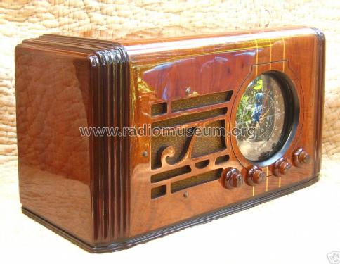
- Mobile in legno
- Radiomuseum.org
- Modello: 5S119 Ch=5516 - Zenith Radio Corp.; Chicago,
- Forma
- Soprammobile con qualsiasi forma (non saputo).
- Dimensioni (LxAxP)
- 20 x 11.5 x 9.1 inch / 508 x 292 x 231 mm
- Annotazioni
-
There is also a version to operate from 25 to 60 Hz and selectable from 95 to 220 V.
- Prezzo nel primo anno
- 45.00 $
- Fonte esterna dei dati
- E. Erb 3-907007-36-0
- Riferimenti schemi
- Rider's Perpetual, Volume 7 = 1936 and before
- Letteratura / Schemi (1)
- -- Original-techn. papers.
- Letteratura / Schemi (2)
- Table Top Radios Vol. 1 Stein 98 (page 168.)
- Altri modelli
-
In questo link sono elencati 4517 modelli, di cui 4109 con immagini e 3652 con schemi.
Elenco delle radio e altri apparecchi della Zenith Radio Corp.; Chicago, IL
Collezioni
Il modello 5S119 fa parte delle collezioni dei seguenti membri.
Discussioni nel forum su questo modello: Zenith Radio Corp.;: 5S119 Ch=5516
Argomenti: 3 | Articoli: 12
Hello! Would appreciate help with the 5S119 I’m restoring.
Here’s where I am:
* All electrolytic and paper capacitors replaced
* All resistors beyond 15% replaced
* All tubes test OK, except 6Q7, awaiting replacement
So, although the 6Q7 is measuring weak in all sections (no shorts), I decided to fire the chassis up with it in place as the replacement hasn’t arrived. I brought it up slowly with the variac/isolation/dim-bulb, and the dial lamps lit and there were no problems with shorts. The only sound produced, though, is a buzz which is there regardless of volume setting. All controls seem to have no effect on sound.
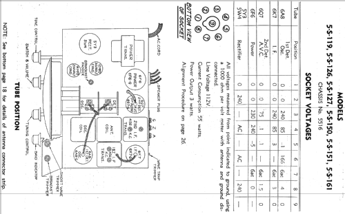
I consulted the “socket voltage” guidelines in the schematic and found the following upon testing the relevant points:
1. 5Y3: 240V AC in, 240V DC out. Appears to be ok.
2. 6F6: Pins 3/4/7 measure correctly, pin 5 is supposed to be -5V, I’m getting -25V
3. 6Q7: Pin 3 is supposed to be 75V, I’m getting 240V. Pins 4/5 should be .1V, I’m getting 2.3V. Pin 7 measures OK. Pin 8 is supposed to be 1.5V, I’m getting 2.4V
4. 6K7: Pin 3 OK at 240V. Pin 4 is supposed to be 85V, I’m getting 112V. Pin 5 measures 0V. Pins 7/8 OK.
5. 6A8 Pin 3 OK at 240V. Pin 4 is supposed to be 85V, I’m getting 115V. Pin 5 supposed to be -1, I’m getting 114V. Pin 6 supposed to be 166, I’m getting 196. Pins 7/8 measure OK.
Measurements were done with the Variac dialed to produce 112V at AC in.
The 6Q7 measures as a bad tube, but even without it in the circuit, I’m still getting 240V at pin 3 where there is only supposed to be 75V.
All voltage tests were also done with the speaker/field coil plugged into circuit. The schematic states that field coil resistance is supposed to be 2125 ohms, but mine measures 852 ohms. The speaker itself states that it is a model 49-165-X rated for 1000 ohms. The schematic states that speaker 49-143-6 is supposed to be the correct speaker. So, perhaps the wrong speaker is included with my radio. Because of the concern of improper field coil resistance, I wired a 2.2K resistor in place of the field coil. With the 2.2K resistor in place, I still had an excess of 230 volts on pin 3 of the 6Q7.
Further, without the field coil/speaker plugged into the chassis, I measure 30V on pin 3 of 6Q7.
Does anyone have any thoughts/suggestions? Although the 6Q7 is measuring weak, I don’t think that’s causing all these voltage anomalies. I’ve rechecked all the values of the resistors and everything appears to be in order there. Could a bad resistor or wrong value resistor be causing the issue? If so, which would be the most likely suspect? Or, is the field coil resistance discrepancy to blame? And why just hum with no volume control? Because the 6Q7 is weak?
Thanks for your help in advance!
Christopher Pallotta, 29.Nov.17
Hello, I'm currently working on restoring a 5S119 and have come across a notation in the schematic that indicates a phono jack input and phono switch. Additionally, there's an alternate drawing of the second detector tube labeled, "Circuit changes for phonograph."
My radio does not have a phono jack/switch and after looking at other photos of this model online, I haven't come across one that does. The circuit changes are very simple though, so it certainly helps if I wanted to add this input. Was it intended that others would do the same themselves using this schematic as a guide or was this actually a factory-supplied option from Zenith?
Any insight appreciated.
Christopher Pallotta, 03.Nov.17
the first tube in the line up of tubes listed is supposed to be a 6A8G and not a 6AB6.
John Allen, 28.Aug.10