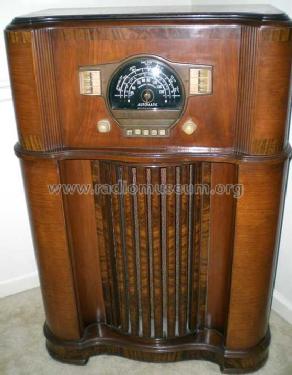
7S558 Chassis 7A02
Zenith Radio Corp.; Chicago, IL
- País
- Estados Unidos
- Fabricante / Marca
- Zenith Radio Corp.; Chicago, IL
- Año
- 1940/1941
- Categoría
- Radio - o Sintonizador pasado WW2
- Radiomuseum.org ID
- 68028
-
- alternative name: Chicago Radio Lab
Beitman

Copy ge. Radio Attic


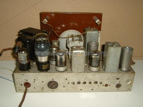
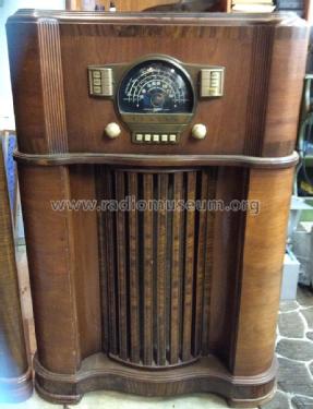
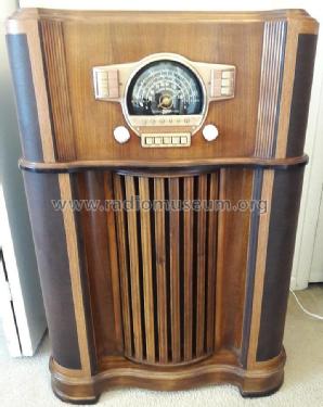
The set belongs to the VRT Omroepmuseum

The set belongs to the VRT Omroepmuseum
The set belongs to the VRT Omroepmuseum

The set belongs to the VRT Omroepmuseum
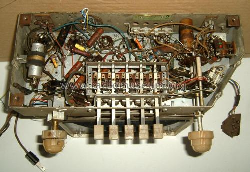
The set belongs to the VRT Omroepmuseum
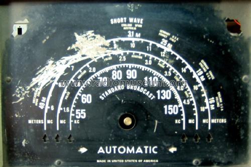
The radio belongs to the VRT Omroepmuseum
Haga clic en la miniatura esquemática para solicitarlo como documento gratuito.
- Numero de valvulas
- 7
- Principio principal
- Superheterodino con paso previo de RF; ZF/IF 455 kHz
- Gama de ondas
- OM y OC
- Tensión de funcionamiento
- Red: Corriente alterna (CA, Inglés = AC) / 115 Volt
- Altavoz
- Altavoz electrodinámico (bobina de campo) / Ø 10 inch = 25.4 cm
- Potencia de salida
- 6.5 W (unknown quality)
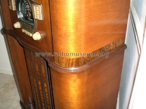
- Material
- Madera
- de Radiomuseum.org
- Modelo: 7S558 Chassis 7A02 - Zenith Radio Corp.; Chicago,
- Forma
- Consola con botonera.
- Ancho, altura, profundidad
- 0 x 41 x 0 inch / 0 x 1041 x 0 mm
- Ext. procedencia de los datos
- Ernst Erb
- Procedencia de los datos
- The Radio Collector's Directory and Price Guide 1921 - 1965
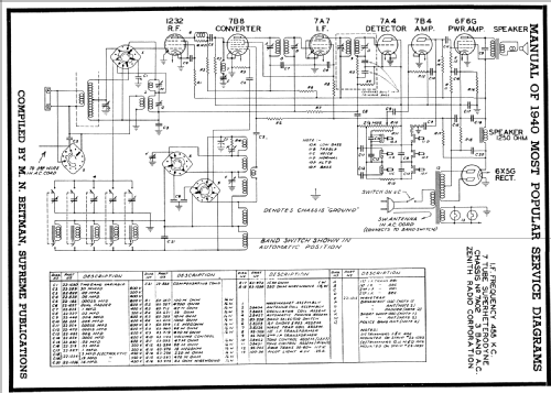
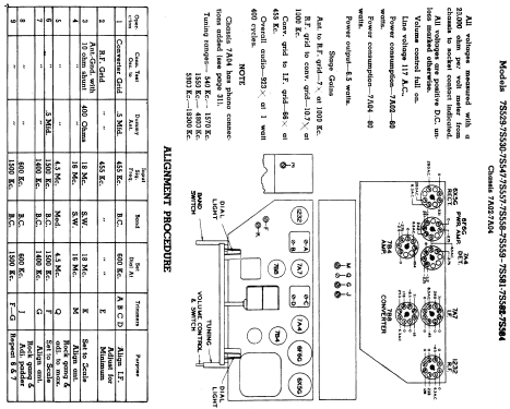
- Referencia esquema
- Rider's Perpetual, Volume 12 = ca. 1941 and before
- Mencionado en
- Collector's Guide to Antique Radios 4. Edition
- Documentación / Esquemas (1)
- Pre-War Consoles
- Otros modelos
-
Donde encontrará 4519 modelos, 4111 con imágenes y 3656 con esquemas.
Ir al listado general de Zenith Radio Corp.; Chicago, IL
Colecciones
El modelo 7S558 es parte de las colecciones de los siguientes miembros.
Contribuciones en el Foro acerca de este modelo: Zenith Radio Corp.;: 7S558 Chassis 7A02
Hilos: 1 | Mensajes: 3
Dear Forum members,
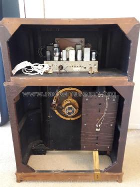
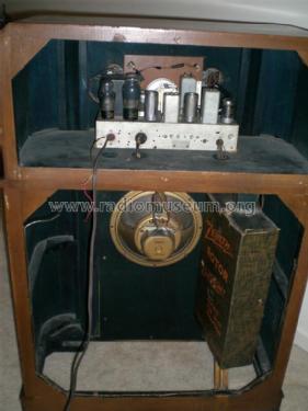
I have a Zenith 7A02 chassis for restauration here. I dowloaded the circuit diagram for this set, and it appears that there is an important difference between this diagram and the chassis i have here. The diagram mentions only two connection points A and G, but the rear ot the radio has a 5-pin connector for the antenna.
This antenna is a Zenith "Rotor Magnet Wave", as you can see on some of the uploaded pictures.
Can anyone provide me withe the correct circuit diagram please?
Thank you
Anexos
- Antenne ingang (299 KB)
Georges Van Campenhout † 28.4.22, 17.Sep.18